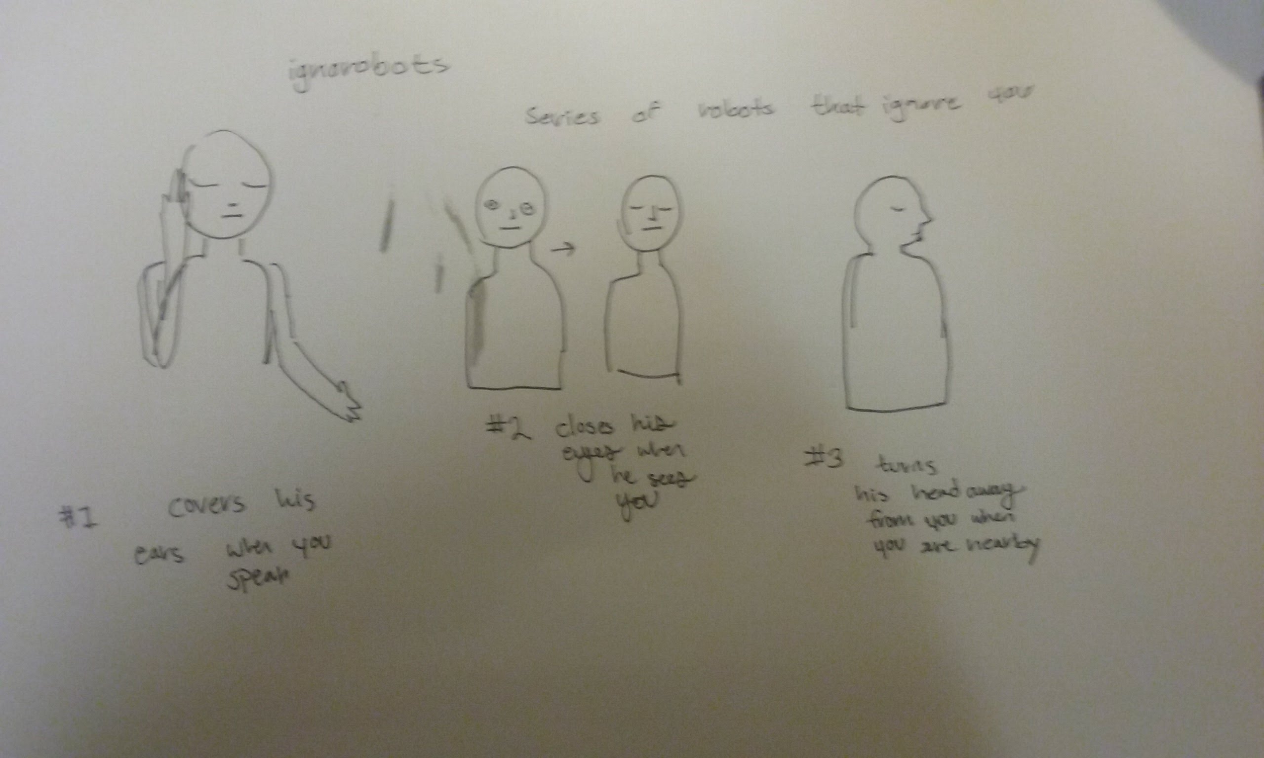
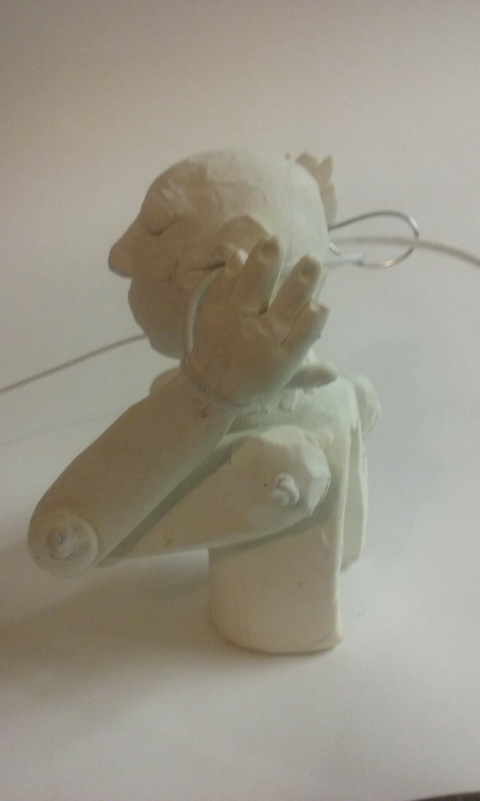
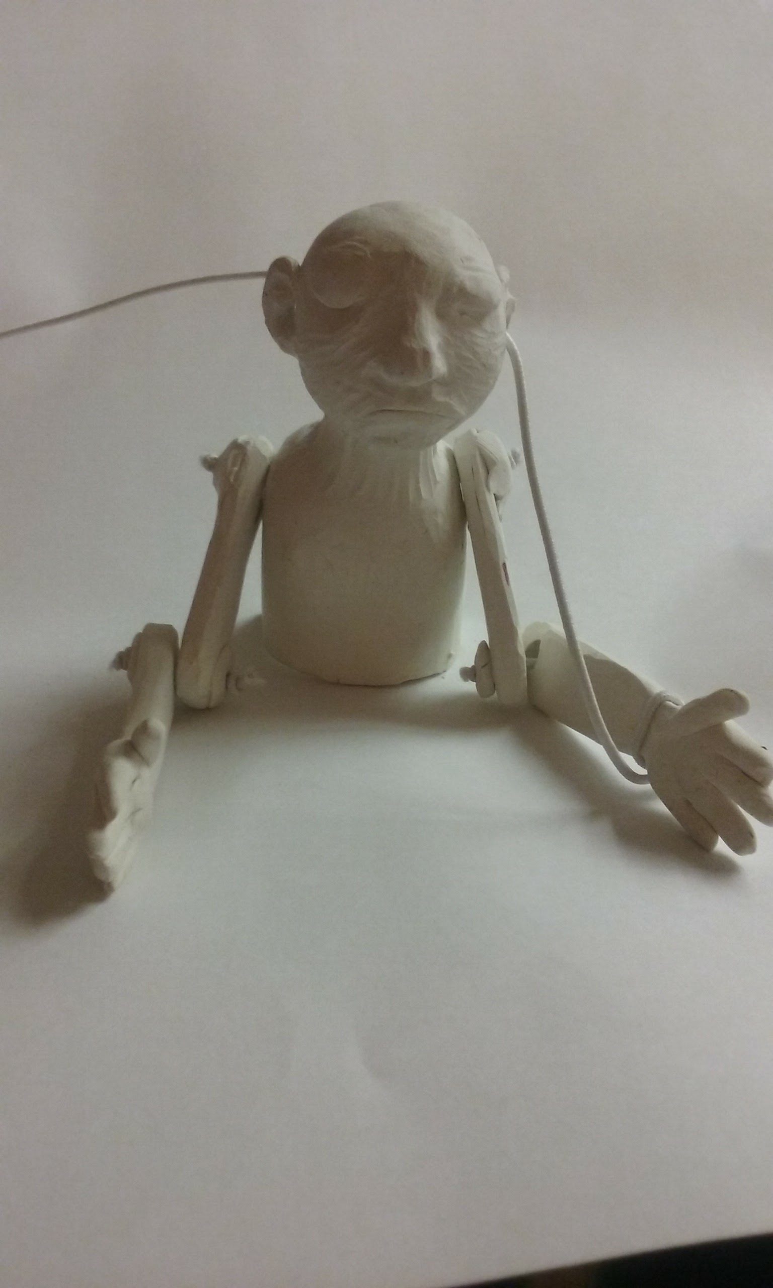
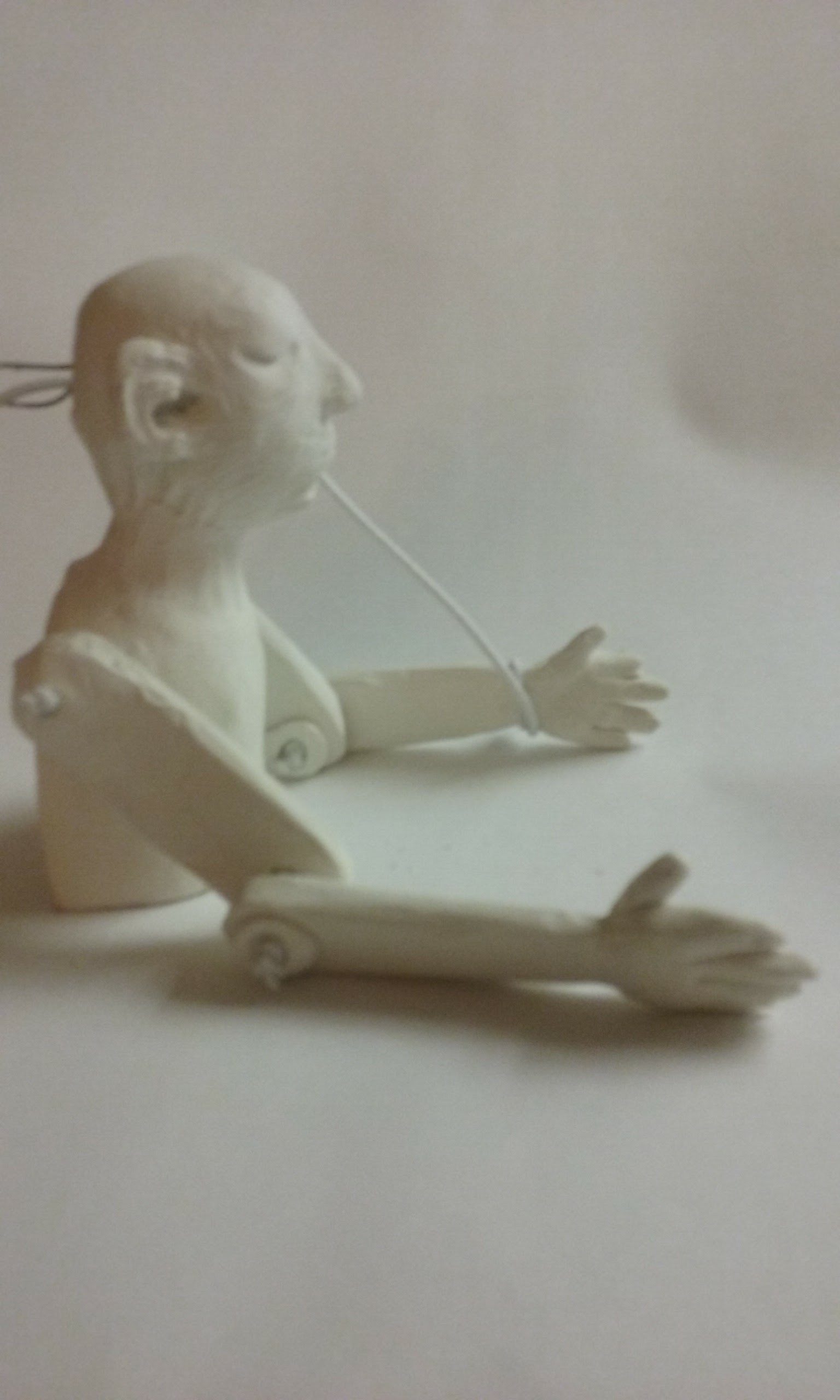
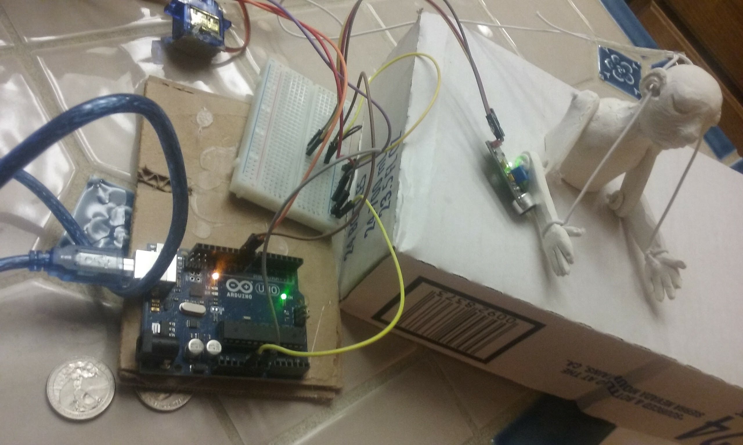
My final project is the first in a set of robots that ignore you.
This one, uses a sound sensor to tell if you are talking, and when it hears you, it covers its ears with its hand. The other one shuts its eyes when it sees you, and the final one turns its head away from you.
/*
* Rui Santos
* Complete Project Details http://randomnerdtutorials.com
*
*
* by BARRAGAN <http://barraganstudio.com>
This example code is in the public domain.
modified 8 Nov 2013
by Scott Fitzgerald
http://www.arduino.cc/en/Tutorial/Sweep
*/
#include Servo.h;
Servo handMovement;
int pos = 0;
int sensorPin=10;
boolean val =0;
void handsUp(){
for (pos = 0; pos <= 90; pos += 1) {
// in steps of 1 degree
handMovement.write(pos);
delay(15);
}
}
void loop (){
val =digitalRead(sensorPin);
Serial.println (val);
// when the sensor detects a signal above the threshold value, he hears you!! hands up
if (val==HIGH) {
handsUp();
}
else {
handsDown(); }
}
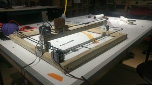
My final project is the Koi fish table. It is basically a Laser Cutter set up. However, I wanted to use wood and acrylic to make the setup so that it would be: 1. cheaper in cost of materials; 2. easier to get materials
The coponent in this project is consist of 2 stepper motors, 3 timing belts, 3 sets of “wheels”, and several wood beams for the structure.
Here is the setup:
When it is running:
Here is the code:
/*This is the Code for controlling the stepper motors
 Some part of the code is adapted from the sample sketch from
 "Stepper Test code from Adafruit tutorial

This code might not work with any other shielf but
 "Adafruit Motor Shield v2"
 ----> http://www.adafruit.com/products/1438
*/


#include <Wire.h>
#include <Adafruit_MotorShield.h>
#include "utility/Adafruit_MS_PWMServoDriver.h"

// Create the motor shield object with the default I2C address
Adafruit_MotorShield AFMS = Adafruit_MotorShield();

// Connect a stepper motor with 200 steps per revolution (1.8 degree)
// to motor port #1(M1 and M2) and another one to #2 (M3 and M4)
Adafruit_StepperMotor *motorX = AFMS.getStepper(200, 2);
Adafruit_StepperMotor *motorY = AFMS.getStepper(200, 1);

int motorSpeed = 100; //# rpm
int XYPosMax = 2000; //200 step per rev, 10 full rev max
int XYPosMin = 0; //whole table is a 2000 by 2000 grid


int curPosX = 0;
int curPosY = 0;

int koiDir = 0;
int koiMove = 0;

int moveX = 0;
int moveY = 0;

int yellowPin = A3;
int bluePin = A0;
int greenPin = A1;
int redPin = A2;

int yellowPre = 0;
int yellowCur = 0;
int greenPre = 0;
int greenCur = 0;
int bluePre = 0;
int blueCur = 0;
int redPre = 0;
int redCur = 0;


int threshHoldDiff = 150;


void setup() {
 // put your setup code here, to run once:
 Serial.begin(9600);
 AFMS.begin(); // create with the default frequency 1.6KHz
 //AFMS.begin(1000); // OR with a different frequency, say 1KHz
 motorX->setSpeed(motorSpeed);
 motorY->setSpeed(motorSpeed);


 yellowPre = analogRead(yellowPin);


}


void touchThePond(){
 yellowCur = analogRead(yellowPin);
 grennCur = analogRead(greenPin);
 blueCur = analogRead(bluePin);
 redCur = analogRead(redPin);

//yellow here (all same setup, different place
 if (abs(yellowCur - yellowPre) > threshHoldDiff){
 //yellow is x = 0, y = 0

moveX = curPosX;
 moveY = curPosY;

 motorX->step(moveX, FORWARD, MICROSTEP)
 motorY->step(moveY, BACKWARD, MICROSTEP)
 }

//blue

//green

//red
}


void moveKoiRand() {
 //First, pick a direction
 //Then decide how much wanna go
 koiDir = random(0, 4); //0 = +X, 1 = -X, 2 = +Y, 3 = -Y
 koiMove = random(50, 401); //small "steps" to mimic fish movement
//
// Serial.print("koiDir = ");
// Serial.print(koiDir);
// Serial.print("; koiMove = " );
// Serial.println(koiMove);
//
// Serial.print("curPosX = ");
// Serial.print(curPosX);
// Serial.print("curPosY = ");
// Serial.println(curPosY);

if (koiDir == 0) {

//check the legality of the position first;
 if ((curPosX + koiMove) >= XYPosMax) {
 moveX = XYPosMax - curPosX; //move to the edge
 }
 else {
 moveX = koiMove;
 }

// Serial.print("in case 0, moveX= ");
// Serial.print(moveX);
 motorX->step(moveX, BACKWARD, MICROSTEP); // moving +X is

curPosX += moveX; //update the new position data;
// Serial.print("in case 0, curPosX= ");
// Serial.println(curPosX);
 }

if (koiDir == 1) {

if ((curPosX - koiMove) <= XYPosMin) {
 moveX = curPosX;
 }
 else {
 moveX = koiMove;
 }

// Serial.print("in case 1, moveX= ");
// Serial.print(moveX);
 motorX->step(moveX, FORWARD, MICROSTEP);

curPosX -= moveX;
// Serial.print("in case 1, curPosX= ");
// Serial.println(curPosX);
 }


if (koiDir == 2) {
 if ((curPosY + koiMove) >= XYPosMax) {
 moveY = XYPosMax - curPosY; //move to the edge
 }
 else {
 moveY = koiMove;
 }
//
// Serial.print("in case 2, moveY= ");
// Serial.print(moveY);
 motorY->step(moveY, FORWARD, MICROSTEP);

curPosY += moveY;
// Serial.print("in case 2, curPosY= ");
// Serial.println(curPosY);
 }

if (koiDir == 3) {
 if ((curPosY - koiMove) <= XYPosMin) {
 moveY = curPosY;
 }
 else {
 moveY = koiMove;
 }

// Serial.print("in case 3, moveY= ");
// Serial.print(moveY);
 motorY->step(moveY, BACKWARD, MICROSTEP);

curPosY = curPosY - moveY;

// Serial.print("in case 3, curPosY= ");
// Serial.println(curPosY);
 }

}


void loop() {
 // put your main code here, to run repeatedly:
 Serial.println("Microstep steps");
 moveKoiRand();


}
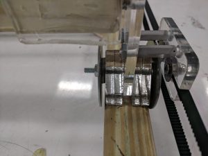
Design of the “Wheel”:
General Idea/Assembly
For the Koi fish holder part
Reflection:
The really hard part of this project is to make the mechanical setup. I spent more than a week working on solidworks. However, the setup is too big and not as percise as I hoped it would be. Therefore, there are a lot of problem while working in the wood shop initially. Later I gave up on following soliworks, and just try and test laser cutting and wood working.
Another part that is complicated is to make the stepper work. The Arduino shield is nice, for controlling the stepper. The libaray it came with helps me to reduced a lot of time for me trying to figure out how to work with stepper (even though it still took a long time for me to understand how stepper works). The other problem that I faced is that the stepper doesn’t come with avaliable datasheet (I coudn’t find anything). However, the shield was nice enough that I tried out a few different voltage input using a controllable power output for the stepper. Finally, I found out that the stepper needs 1.5A at 5V which is a lot higher than normal power supply. At last I used 2.4A at around 8V to power the stepper to make sure it can over come the friction it might experience.
The problem that I didn’t really solve in this project is how to change the stepper speed. Even the Adafruit library include speed settings, the stepper speed couldn’t be changed for some reason.
If I were to do this project again, I will add a set of caliberation setting. I will mount limit switches on the zero of X and Y axis. So I don’t need to hand calibrate to zero position everytime it restarts. However, that need me to figure out how to program the stepper to move without having to tell it how much it needs to move.
I set out to make some kind of machine that could draw using XY coordination, with the idea that it should also have interchangeable drawing heads, some of which would also have motorized components of their own (for example an attachment that would swing a drawing pencil back and forth in strokes, while itself being moved through XY axis plotting). I also wanted to program the machine such that it could be controlled with manual knobs, programmed with patterns to follow, or set to follow a vector image file.
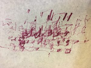
I didn’t achieve all of these things, but I did assemble a functional XY axis plotter from scratch. One thing I vastly underestimated was the amount of time it would take to make, test, and adjust the mechanical components of the machine (that is, almost the full time of making the project). I also had trouble with getting the right kinds of motors, the first one I used wasn’t actually a stepper, and I had to cut it out and replace it. Then I found that the motors I had finally put in were not 360 degree steppers, which is what I really needed to have the components move back and forth as far as they were physically able, so the machine’s full plotting range was smaller than intended.
I also went the quick and dirty route, using cut cardboard and hot glue, pulley systems made with bolts as axels and makeshift sprockets rigged out of shaped wired. This meant the machine stuck and jittered a lot. In some ways this was expected, and also a happy accident. Any 3D printer or similar plotting apparatus could give me close to perfect XY movement, but this machine was more… shall we say, personal. No matter how well the XY plotting software was made, any drawing it made would be filled with mistakes where the marker caught on the paper, or the carriage got stuck for a moment, or the fishing line didn’t engage with the top motor as strongly as the bottom one. This I think makes for a more artistically interesting interaction between machine and mark making. I want this thing to be obviously incapable of drawing anything like a person could. I want it to draw in a way that only a fucked up robot could. I think if I tried to make a similar thing in the future I would make it out of dumber and more intentionally haphazard materials.
My project was to create corresponding colored gloves to alter light in an environment. Initially I wanted to make something large scale where a room could detect what color clothing you are wearing and adapt accordingly. Unfortunately due to time a feasibility I had to scale down the project. I went through trial and error to incorporate a phillips hue and a particle photon but after much chagrin I had to use a RGB LED strip. Each of the gloves will trigger the lights to change to what ever color the glove is. I used imbedded RFID tags in the gloves.
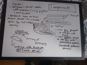
I intended to create an 2D array of solenoids that would respond to changes in depth input through a kinect. It would essentially reflect the depth in the image captured by the kinect. However, I found it very difficult to take input from the kinect and send this data to the arduino simultaneously, so instead I first record a history of depth data from the kinect, and then send it to the arduino via bluetooth, which it then uses to move the solenoids.
I created CAD models (in the files attached with this submission), which consisted of three acrylic tiles per solenoid. The two below would have had holes in them to allow the solenoid to move. However, the 5V solenoids I had planned using grew legs and walked away, and this design was inapplicable to the 7V solenoids I ended up using. (the brainstorming process and design is attached with this submission)
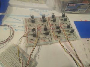
Circuitry:
circuit board I made for 4×4 array of 5V solenoids:
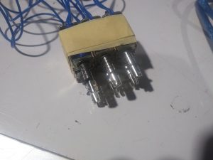
finished 2×3 array of 7V solenoids I was forced to use:
Issues I faced:
I spent a lot of time trying to figure out how to get depth values from the kinect. I also had a lot of issues with serial connection between my laptop (mac)and the arduino. I finally somewhat resolved this by using software serial with bluetooth. However, as previously mentioned, I had to write another script in python to send the data across the serial connection.
I was scavenge for and use 7V solenoids instead of the 5V ones as I had initially planned. This took additional time and configuring.
Acknowledgements:
I would like to thank ideate for providing me with the parts, Akshat Prakash for helping me with the software serial, and Bolaji Banakole for giving me his spare arduino when I fried mine.
My initial project idea was to just make an instrument that makes people think by being not unlike what people expect. I decided to make a keyboard which looked exactly like a functioning proper keyboard but emitted noise that were slightly off. While the major idea remains the same, I noticed that this would be a very interesting model to mimic very real occurrences of things and people having perfect external appearances but functioning in confusing ways. The keyboard I have finally made is very confused most of the time, playing notes with frequencies slightly off, with tones that are varied, with different and dynamically varying magnitudes. All of this happens without any apparent pattern. However, every so often there is a period of lucidness that can be experienced where the keyboard plays exactly like one would expect. To someone who reads and learns about neurodegenerative diseases, this is a very relatable phenomena.
Components:
An old Yamaha Keyboard
Conductive Copper Foil Tape – Switches
8 ohm Speaker
Wire
10k and 15k ohm Resistors
Arduino Teensy
Class D Amplifier
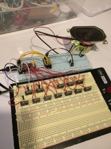
Iterations
The first draft of this project was conducted with just a couple of breadboards, lever switches, and an Arduino Teensy using the DAC to output waveforms. A code was implemented to dynamicallyh randomize the kind of notes played on each key to show a proof of concept of how the project would work. The image below shows what the circuit looks like.
The Final Project
I decided to try and obtain an actual keyboard to use as a shell and the form for my project. I had two options on how to move forward with it – 1. to access the key reads using the circuits that exist on the keyboard and, 2. to completely rip out all the electronics and implement simply design switches to read using the Teensy. The latter option was selected because it proved to be slightly complicated to figure out the wiring of the keyboard’s electronics. Also, I decided to implement only an octave worth of keys but focus more on the software of the sounds generated by the keyboard. A limitation of the Teensy is also the number of inputs.
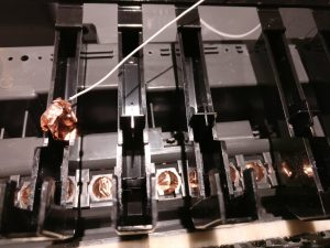
The switches were implemented using Copper Foil tape applied on the keys and in a power line running in the bottom where the keys would make contact as seen in the image below.
A challenge I ran into was on understanding how to make these switches function in a more reliable manner. I found that reinforcing the foil by applying multiple layers was really helpful.
The code is uploaded here. I think it was really interesting to use a DAC to produce waveforms and directly manipulate them to create various effects.
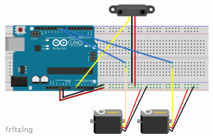
For my final project, I made a responsive worm that normally wiggles around on the ground, but when a person comes too close then will look up at the person.
The main challenges for this project was trying to keep the form factor I wanted it – I really wanted the worm to be lasercut wood but getting the wood to bend at the appropriate angle took a fair amount of testing. I found a solution by using two servos that pull the the wood back and keep it in place. Finally, the aesthetics took a good deal of time to try to cover up the circuitry and motors to make it just look like a worm in a tank.
The circuitry and code in itself was quite simple – an analog IR sensor and two servos that pull at string that actuates the worm. However, I think this was a good strategy because of how many iterations the worm movement took to look somewhat good.
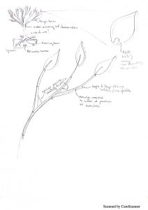
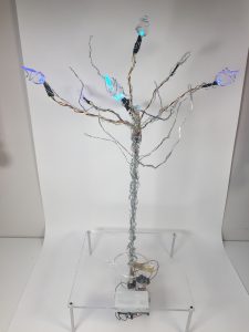
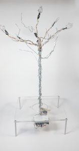
[cc]My original idea was inspired by the ever-changing and unpredictable weather of Pittsburgh. I wanted to create a visually appealing piece that would be able to portray this weather regardless of the season or time of year. My first sketch relied heavily on servos and moving parts, however, in my final project I decided to streamline my design.
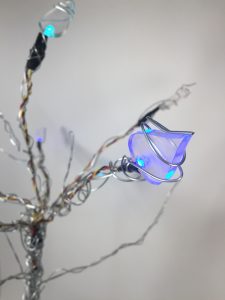
This final product is hooked up to a live feed HTML website that I wrote to retrieve the weather forecast. The Arduino then interprets the data and converts the information into a visual display of the different type of season that the current weather might reflect.
There are four seasons that the tree can portray, Summer, Fall, Winter, and Spring. The tree rotates and displays different colored leaves depending on what season we would traditionally associate with the current weather regardless of the actual time of year.
My concept is to be able to have this display in my room and act as a visual representation of the weather so that I can get ready in the morning with an accurate idea of the weather in Pittsburgh regardless of its often deceptive appearance.
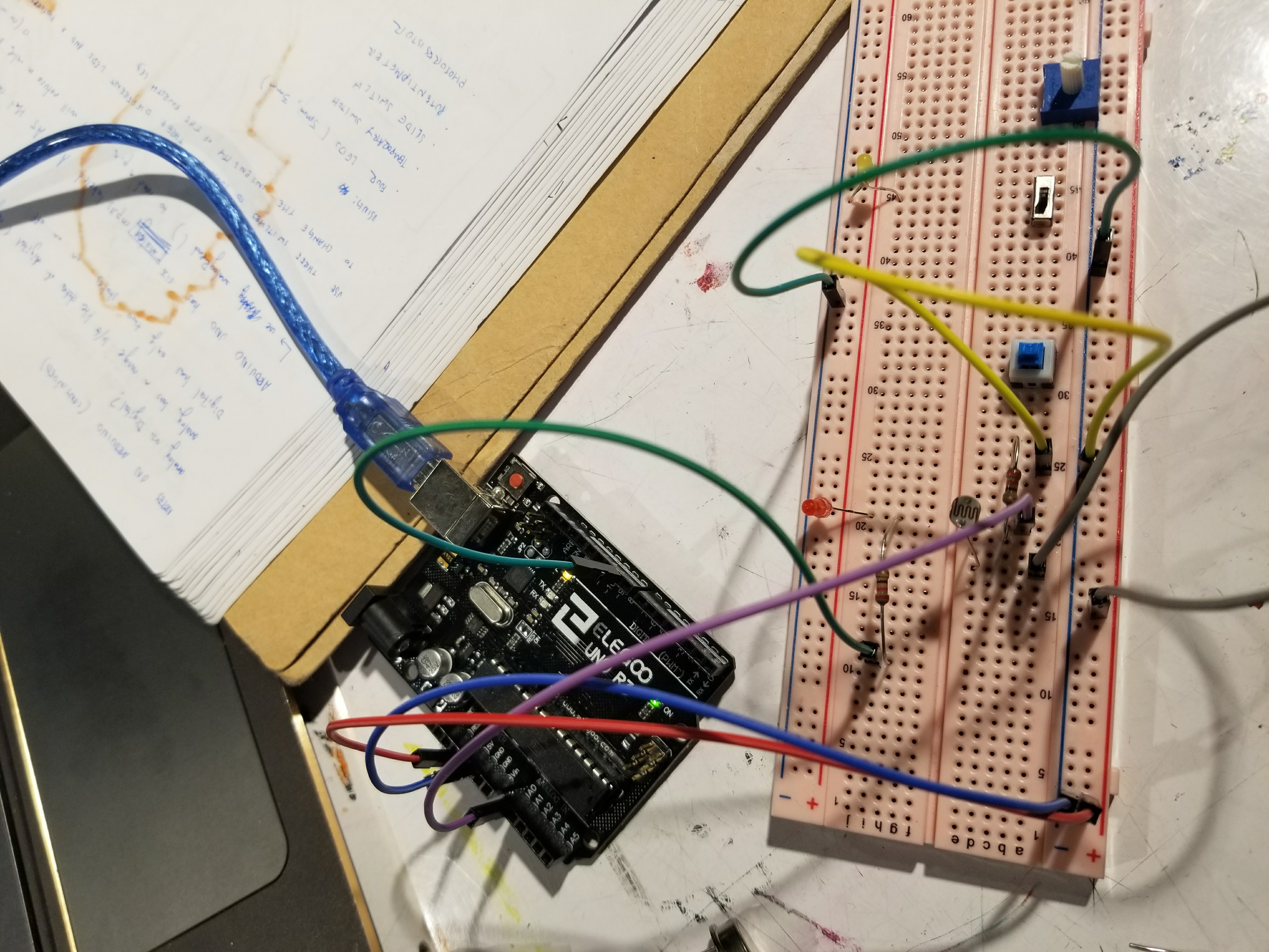
I connected three LEDs on the breadboard to a three pole switch, a photoresistor, and a 10K ohm resistor.
I found this difficult at first because I didn’t realize that red and white LEDs needed different current run through them. I tried with and without the resistor and adjusted brightness afterwards.
Once I got the simple circuit working, I attached the buttons into the circuit.
This was difficult because I got the photo resistor working independently, but not with the other components.
Hi hello, so for my final project, I wanted to create a multi-person interactive experience so I decided to attach both photoresistors and distance sensors to my lamp.
The experience involves two users, one equipped with their smartphone flashlight and the other controlling the Y-height depending on distance.
To begin, I decided to give myself small goals that I should check off by the time of the rough crit.
get servo working
get light bulb working
lasercut shade, and chassis
get the light bulb communicating with the photoresistor
As of now these individual components are working, but naturally the hardest part is getting them to communicate with each other.