Assignment 7 – Rough Crit – Tatyana Mustakos

For my rough crit, I made an automaton that moves its head and hand. It also has shoulder rotation that allows it to rotate its arm, and well as tendons which allow it to reach out/ retract.

https://photos.app.goo.gl/khiN5u3OMJzX4H7g2

https://photos.app.goo.gl/4w65Jl4bumMZOUW33

I made the face and hand out of paperclay, and the arm and body out of cardboard for this version. I will construct the final completely out of paper clay so that the aesthetics are more cohesive.

For the final version I want to have it so that the piece is still, but once someone holds their hand out to it, it looks up a bit and reaches out to touch their hand

code:

/*
* servo movement
* Tatyana Mustakos
*/

#include

Servo myservo; // create servo object to control a servo
// twelve servo objects can be created on most boards
Servo myservo1;

int pos = 0; // variable to store the servo position
int pos1 =0;
void setup() {
myservo.attach(9); // attaches the servo on pin 9 to the servo object
myservo1.attach(10);
}

void loop() {
for (pos = 0; pos = 0; pos -= 1) { // goes from 180 degrees to 0 degrees
myservo.write(pos); // tell servo to go to position in variable ‘pos’
delay(15); // waits 15ms for the servo to reach the position
}

for (pos1 = 0; pos1 = 0; pos1 -= 1) { // goes from 180 degrees to 0 degrees
myservo1.write(pos1); // tell servo to go to position in variable ‘pos’
delay(15); // waits 15ms for the servo to reach the position
}
}


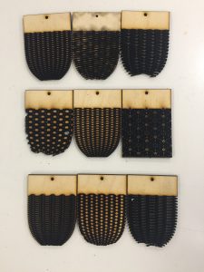
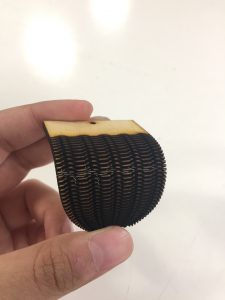
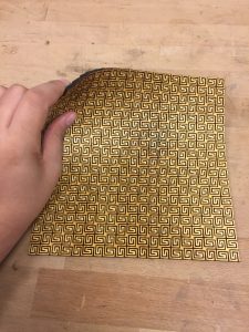
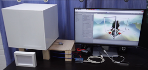
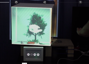
My other project (sorry i couldnt pick) is a radial plotter, it draws images but is restricted to only curved brush strokes. the pen is attatched to an arm that can extend or retract (this affects the distance from the plotter itself, or the origin point), and can rotate side to side. This project is an experimentation of a sort of reverse computer vision, instead of traditional vector plotters, I wanted to focus more on the brush stroke (fake sketch prototype below)

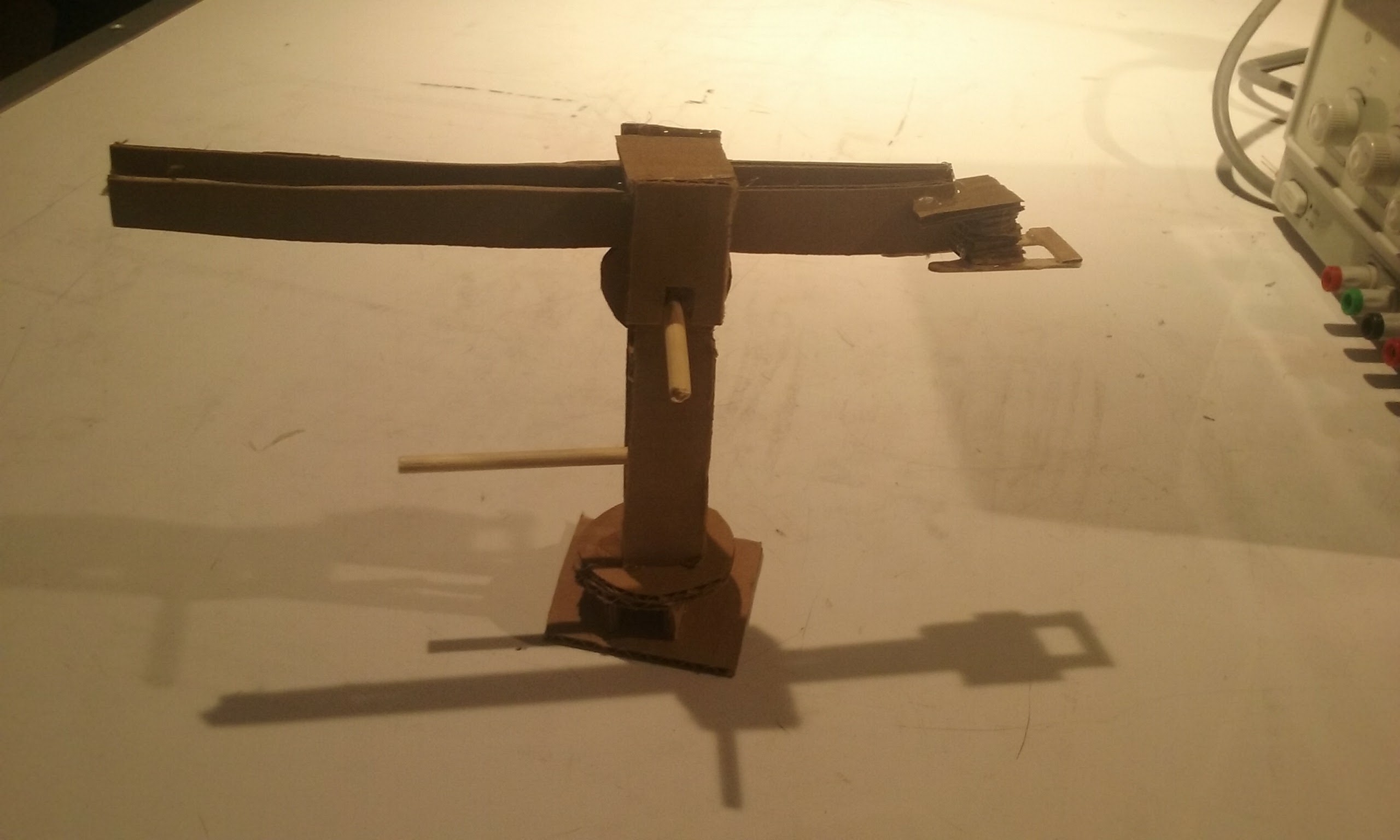
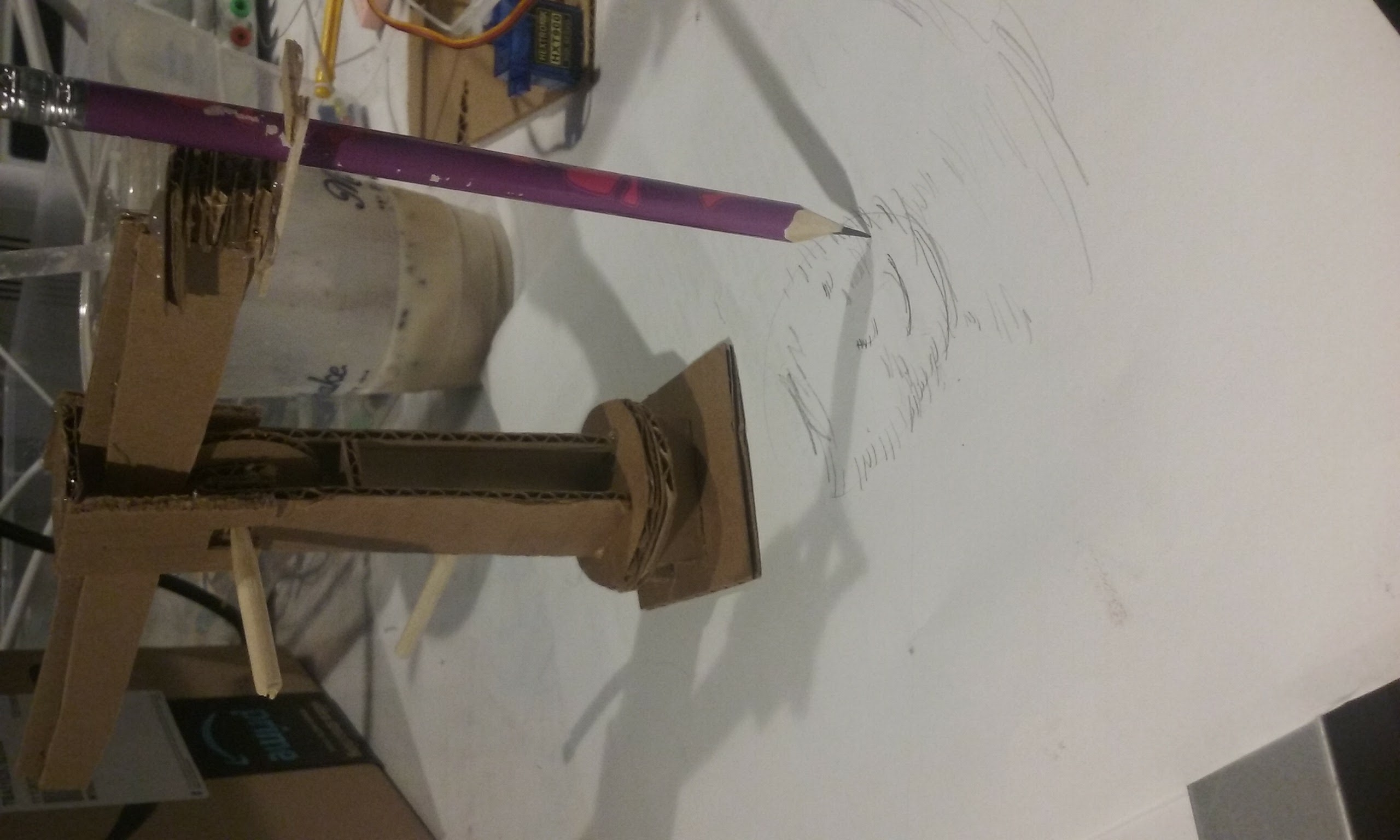
I created a working(aside from the gear and inward rotary) prototype that extends and rotates around the base axis. I have working pieces and will laser cut them so that they function smothely. The arm can extend due to a motor rotating the gear, the pen will move up and down based on an actuator (with a mechanism simiair to a pen clicker), and the base will rotate with a servo (since it doesnt need to rotate more than 180 degrees).

I will implement drawing through processing and the load pixels function, calculating which line/curve segments the plotter should draw.

Another interesting thing that will occur is seeing what will happen/ how the image will draw differently based on where the plotter is placed


Final Project – Rough Crit

For my rough crit, I have a prototype of the mechanical “worm” that can move in a couple of dimensions and is actuated by the Arduino. Moreover, I have also ensured that I can get data from an IR sensor and a microphone, but will need to choose which sensor to use based on the final form of my tank.

The mechanical form took a great deal of prototyping to figure out a good mix of flexibility (especially in multiple angles) as well as durability, as I found out rather painfully that many of these patterns broke rather quickly. Moreover, another trade off became very apparent with weight and movement, as not only did it require more strength to move but also it means I have to tamp down the other part of the board.

Additionally, I had originally planned to actuate the system using muscle wire, but it ended up being too weak to move the worm. Therefore, as a work around, I actuated the worm using string and servo motors – the servo motors pull up the string, which are attached to specific points around the worm and then pull up the worm accordingly.

However, I’m trying to get a more natural movement, so I might have magnets on the underside of the wood so that way there is only a small part of the wood that peeks up with every string.

Code: prototype

Bryt 2.0: A Music Visualizer (Project Proposal)

Concept: 

A box-like music visualizer  and music player that uses LEDs and mirrors t0 create a a visual representation of music. Users will be able to interact the with the device by changing the colors of the lights as well as being able to use headphone jack enabled devices to select the music being visualized.

LEDs will be attached to the edge of the mirror to recreate this effect. Except 4 will be used to create a 3-dimentional cube full of endless mirrors!

Hardware:

  • 3D printed frame for the mirrors (box-like for the device)
  • Mirrors (4 or 5)
  • LED strips
  • power source, battery
  • headphone adapter
  • sliding potenntiometer (change colors of lights)

Software:

  • Library for sound interpretation (getting inputs for music)
  • RGB led control (actual visualization)
  • Library for playing sounds (enabling the device to play music)

Order of Construction and Testing:

  1. RGB light control
  2. Sliding potentiometer control
  3. RGB control with potentiometer
  4. Play music with arduino by input from audiojack
  5. Interpret Music currently being played
  6. Visualize interpreted music
  7. 3D print box frame,
  8. Attach mirrors
  9. Attach speakers
  10. Attach arduino, audiojack, and other inputs
  11. Polish

Final Project Proposal: One of Two options

I explored a couple other ideas and included them just to show my process.

https://samanthaho.myportfolio.com/final-project

My actual project proposal is to make an interactive lamp that requires a group of people to coordinate with each other. The lamp shade itself will be lasercut be on a vertical track. One person of the team controls the vertical height of the shade and the other, the brightness of the bulb.

The height of the shade will directly correspond with person A and how far away they are from the lamp. Similarly, person B will need to take their phone out and use their phone light to control the brightness of the bulb via photoresistor.

It requires the coordination of  both parties to properly project shadows and silhouettes onto the table.

The Indexical Mark Machine

I want to make a drawing machine.  What interests me about machines drawing is rhythms in mark making, rather than accuracy and depiction.  I think what’s beautiful about mechanical drawing is the pure abstraction of endless uniform marks done in a pattern, simple or complex, that is evidence of the same motion done over and over again.  
I feel what’s most beautiful about all art is the presence of the indexical mark: the grain of a brush stroke, the edge and slight vibrations in a line of ink that prove it was drawn with a human hand, or the finger prints in a clay sculpture.  I make the case that the difference between artistic media is defined by indexical marks.  Do two works have different indexical marks?  Then they are different forms of art entirely, showing us different aspects of compositional potential.

So I want to invent new indexical marks, ones that the human hand is not capable of producing.  I want to see patterns fall out of a mechanical gesture that I built, but didn’t anticipate all the behaviors of, and to capture a map of these patterns on paper.


I don’t care if the machine can make a representational image; rather I want to make a series of nodes and attachments that each make unique patterns, which can each be held by mechanical arms over a drawing surface, each hold a variety of drawing tools, and be programmed into “dancing” together.

Hardware

  • 5 V stepper motors
  • 12 V Stepper motors
  • 12 V DC motors
  • Sliding potentiometers; light and sound sensors (I want the frequencies of the mark making mechanisms to be adjustable by both controlled factors and factors influenced by the environment. )
  • Controller frame
  • Card board for prototyping the structure of the machine
  • Acrylic to be laser cut for the final structure


Software

  • Built from the ground up.  The most complex programing will be that of the arms which position the drawing attachments over different places on the drawing surface.  I may use a coordinate positioning library for a configuration of motors that pushes and pulls a node into various positions with crossing “X and Y” arms.


Timeline


  • Weeks 1 and 2

Make several attachable drawing tool mechanisms which each hold a drawing tool differently, and move it about in a different pattern.


  • Week 3

Build a structure that holds the attachable nodes over a drawing surface, with the capability of arms to move the nodes across different areas of the surface.


  • Week 4

Control board and sensory responders that can be used to change patterns of the arms, and the nodes.


  • Week 5

Program built-in patterns that the controls will influence factors of.

  • Week 6

Make some more nodes, and make some drawings!

Project Proposal: Fishies

Concept statement:

I plan on making an automatic fish feeder/ pump system that responds to texts (or emails, or some similar interaction) – certain key phrases will trigger specific responses in the system. I want to use this project to synthesize a more human interaction between people and their fish — while texting isn’t the most intimate form of communication, it’s such a casual means of talking to other people that I think it will be useful in creating an artificial sense of intimacy.

Hardware: some sort of feeding mechanism (motor-based?), submersible pump (small), lights (LEDs), fish tank, fish (I already have the last two, don’t worry)…. I’m not sure what I’d need to connect w/ an arduino via sms or through wifi

Software: I’ll need software to make the arduino respond to texting (or something similar),  and then perform fairly straightforward mechanical outputs

Order of constructing and testing: first I need to get the arduino response down pretty well, since the project largely hinges on that, then creating a feeding mechanism will be the next priority… everything after that will largely be “frills”/things that aren’t crucial to the project. As I add components, I’ll need to figure out how to display them non-ratchetly. I’m also definitely going to need constant reminders to document my process.

Final Project Proposal

Abstract

I’d like to make an interactive 3D drawing box. Users can draw an object in 3d space and see their drawing projected onto an interactive cube in real time. It will use Unity, Arduino, a projector, and the Leap Motion Sensor. It is heavily inspired by Ralf Breninek’s project: https://vimeo.com/173940321

As well as Leap Motion’s Pinch Draw:

Image result for pinch draw leap motion

Unfortunately, Pinch Draw is currently only compatible with VR headsets, so it won’t translate directly to my project idea. That’s where I think some of the technical complexity comes in- I will probably have to write my own custom program.

Hardware

  • Projector
  • Cube (made from white foam core)
  • Stand for cube
  • Stepper motor
  • Arduino
  • Leap Motion Sensor
  • Power supply

Software

  • Uniduino
  • Unity
  • Firmata for Arduino
  • Arduino

Order of Construction and Testing

  1. Order supplies and follow tutorials for 3D drawing tutorials for Unity
  2. Connect projector to computer and figure out dimensions/projection logistics for program
  3. Build projection cube
  4. Use Firmata and Uniduino to control Arduino and motor based on Unity output
  5. Put whole project together: project Unity game onto cube, have cube respond to hand gesture commands, finalize user interface
  6. Information poster and artist’s statement for final show