Final Project – Koi Fish Table

My final project is the Koi fish table. It is basically a Laser Cutter set up. However, I wanted to use wood and acrylic to make the setup so that it would be: 1. cheaper in cost of materials; 2. easier to get materials

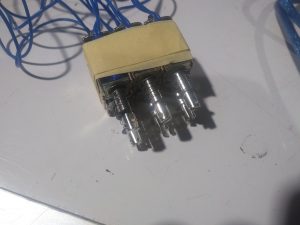
The coponent in this project is consist of 2 stepper motors, 3 timing belts, 3 sets of “wheels”, and several wood beams for the structure.

Here is the setup:
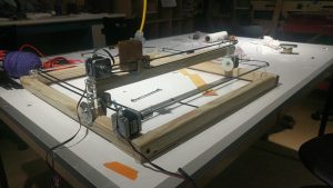
When it is running:


Here is the code:

/*This is the Code for controlling the stepper motors
 Some part of the code is adapted from the sample sketch from
 "Stepper Test code from Adafruit tutorial

This code might not work with any other shielf but
 "Adafruit Motor Shield v2"
 ----> http://www.adafruit.com/products/1438
*/


#include <Wire.h>
#include <Adafruit_MotorShield.h>
#include "utility/Adafruit_MS_PWMServoDriver.h"

// Create the motor shield object with the default I2C address
Adafruit_MotorShield AFMS = Adafruit_MotorShield();

// Connect a stepper motor with 200 steps per revolution (1.8 degree)
// to motor port #1(M1 and M2) and another one to #2 (M3 and M4)
Adafruit_StepperMotor *motorX = AFMS.getStepper(200, 2);
Adafruit_StepperMotor *motorY = AFMS.getStepper(200, 1);

int motorSpeed = 100; //# rpm
int XYPosMax = 2000; //200 step per rev, 10 full rev max
int XYPosMin = 0; //whole table is a 2000 by 2000 grid


int curPosX = 0;
int curPosY = 0;

int koiDir = 0;
int koiMove = 0;

int moveX = 0;
int moveY = 0;

int yellowPin = A3;
int bluePin = A0;
int greenPin = A1;
int redPin = A2;

int yellowPre = 0;
int yellowCur = 0;
int greenPre = 0;
int greenCur = 0;
int bluePre = 0;
int blueCur = 0;
int redPre = 0;
int redCur = 0;


int threshHoldDiff = 150;


void setup() {
 // put your setup code here, to run once:
 Serial.begin(9600);
 AFMS.begin(); // create with the default frequency 1.6KHz
 //AFMS.begin(1000); // OR with a different frequency, say 1KHz
 motorX->setSpeed(motorSpeed);
 motorY->setSpeed(motorSpeed);


 yellowPre = analogRead(yellowPin);


}


void touchThePond(){
 yellowCur = analogRead(yellowPin);
 grennCur = analogRead(greenPin);
 blueCur = analogRead(bluePin);
 redCur = analogRead(redPin);

//yellow here (all same setup, different place
 if (abs(yellowCur - yellowPre) > threshHoldDiff){
 //yellow is x = 0, y = 0

moveX = curPosX;
 moveY = curPosY;
 
 motorX->step(moveX, FORWARD, MICROSTEP)
 motorY->step(moveY, BACKWARD, MICROSTEP)
 }

//blue

//green

//red
}


void moveKoiRand() {
 //First, pick a direction
 //Then decide how much wanna go
 koiDir = random(0, 4); //0 = +X, 1 = -X, 2 = +Y, 3 = -Y
 koiMove = random(50, 401); //small "steps" to mimic fish movement
//
// Serial.print("koiDir = ");
// Serial.print(koiDir);
// Serial.print("; koiMove = " );
// Serial.println(koiMove);
//
// Serial.print("curPosX = ");
// Serial.print(curPosX);
// Serial.print("curPosY = ");
// Serial.println(curPosY);

if (koiDir == 0) {

//check the legality of the position first;
 if ((curPosX + koiMove) >= XYPosMax) {
 moveX = XYPosMax - curPosX; //move to the edge
 }
 else {
 moveX = koiMove;
 }

// Serial.print("in case 0, moveX= ");
// Serial.print(moveX);
 motorX->step(moveX, BACKWARD, MICROSTEP); // moving +X is

curPosX += moveX; //update the new position data;
// Serial.print("in case 0, curPosX= ");
// Serial.println(curPosX);
 }

if (koiDir == 1) {

if ((curPosX - koiMove) <= XYPosMin) {
 moveX = curPosX;
 }
 else {
 moveX = koiMove;
 }

// Serial.print("in case 1, moveX= ");
// Serial.print(moveX);
 motorX->step(moveX, FORWARD, MICROSTEP);

curPosX -= moveX;
// Serial.print("in case 1, curPosX= ");
// Serial.println(curPosX);
 }


if (koiDir == 2) {
 if ((curPosY + koiMove) >= XYPosMax) {
 moveY = XYPosMax - curPosY; //move to the edge
 }
 else {
 moveY = koiMove;
 }
//
// Serial.print("in case 2, moveY= ");
// Serial.print(moveY);
 motorY->step(moveY, FORWARD, MICROSTEP);

curPosY += moveY;
// Serial.print("in case 2, curPosY= ");
// Serial.println(curPosY);
 }

if (koiDir == 3) {
 if ((curPosY - koiMove) <= XYPosMin) {
 moveY = curPosY;
 }
 else {
 moveY = koiMove;
 }

// Serial.print("in case 3, moveY= ");
// Serial.print(moveY);
 motorY->step(moveY, BACKWARD, MICROSTEP);

curPosY = curPosY - moveY;

// Serial.print("in case 3, curPosY= ");
// Serial.println(curPosY);
 }

}


void loop() {
 // put your main code here, to run repeatedly:
 Serial.println("Microstep steps");
 moveKoiRand();


}


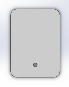
Design of the “Wheel”:
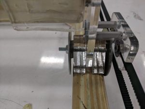
General Idea/Assembly


For the Koi fish holder part


Reflection:

The really hard part of this project is to make the mechanical setup. I spent more than a week working on solidworks. However, the setup is too big and not as percise as I hoped it would be. Therefore, there are a lot of problem while working in the wood shop initially. Later I gave up on following soliworks, and just try and test laser cutting and wood working.

Another part that is complicated is to make the stepper work. The Arduino shield is nice, for controlling the stepper. The libaray it came with helps me to reduced a lot of time for me trying to figure out how to work with stepper (even though it still took a long time for me to understand how stepper works). The other problem that I faced is that the stepper doesn’t come with avaliable datasheet (I coudn’t find anything). However, the shield was nice enough that I tried out a few different voltage input using a controllable power output for the stepper. Finally, I found out that the stepper needs 1.5A at 5V which is a lot higher than normal power supply. At last I used 2.4A at around 8V to power the stepper to make sure it can over come the friction it might experience.

The problem that I didn’t really solve in this project is how to change the stepper speed. Even the Adafruit library include speed settings, the stepper speed couldn’t be changed for some reason.

If I were to do this project again, I will add a set of caliberation setting. I will mount limit switches on the zero of X and Y axis. So I don’t need to hand calibrate to zero position everytime it restarts. However, that need me to figure out how to program the stepper to move without having to tell it how much it needs to move.
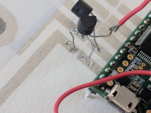


Final Project: Capacitive Touch Activated Screen Print

Screen printing has been an influential and power medium of communication for about 1000 years. This basic touch-test shows the medium can be turned into a method for interactive communication.

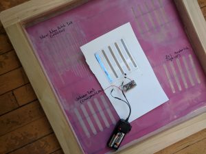
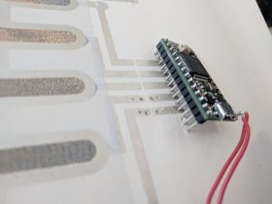
This piece displays an interactive light up screen print attached to the polyester stencil that was used to print the circuit. A Teensy 3.2, two triacs, and a DC-AC inverter power source created the artwork.

The screen is used to hold each component in place and display each shape layer of the printed circuit

The power source, run from two AA batteries, produces ~200 volts AC. The Teensy runs from a separate power source. Triacs, a component that acts as a transistor to switch on or off AC, is attached to the Teensy for modulation, and bridges the printed light up segment to a ground.

This piece attempts to use the ink circuitry to press-fit the Teensy to the wires that connect to the triacs

This method is unreliable because the paper stretches and loses electrical connection quite easily.

Touch activated electroluminescent screen print.

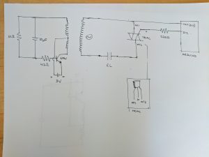
Schematic, code below.

Code:

final.ino

Assignment 08: Hourglass

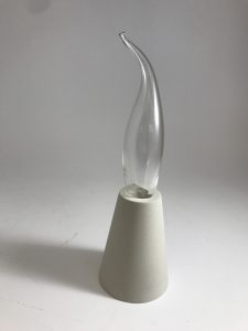
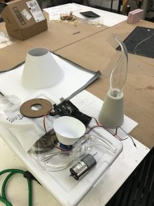
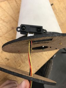
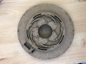
My final concept is a representation of time as an organism. This responsive hourglass changes how fast time passes when you ‘notice it’. This is done using an IR sensor that interprets distance as a specific state. This state causes a servo to move a specific distance and change the diameter of an aperture. This would then affect the speed in which the sand falls out of the glass.

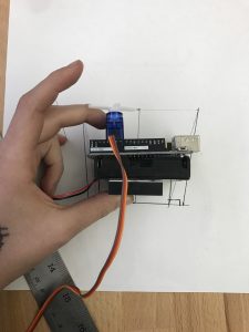
Unfortunately I was not able to get the entire piece working. There is a structural issue that I did not realize until the entire piece was together. Although the mechanics and code work, the weight on the aperture requires a lot of force from the servo. Even though I tried different sized servos, none were strong enough to move the latch of the aperture.

Code and Fritzing: sketch_assignment-08-hourglass-brennan

Process:


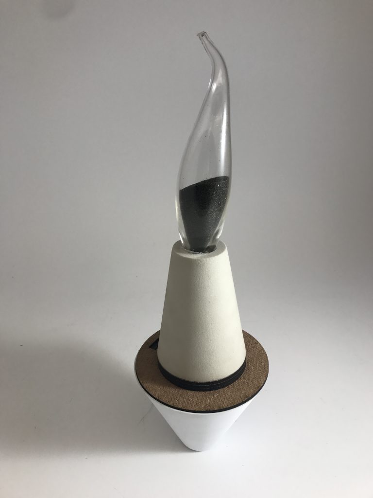
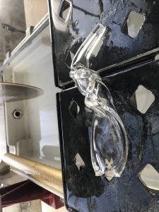
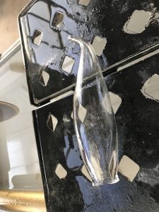
I blew a few glass forms to be used to hold the sand. I had to trim them in order for the sand to travel through both ends. Unfortunately I had to simplify my concept and have it exist in only one state. I had to make a lot of form adjustments after blowing the glass. This caused a lot of constraints because of the strength of the glass and how it could connect to the rest of the form.  In addition, my intention was for the glass to be larger, so the form that holds the arduino would not feel so large in comparison.


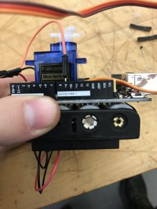
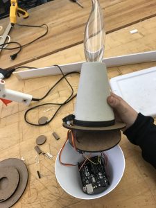
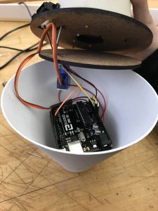
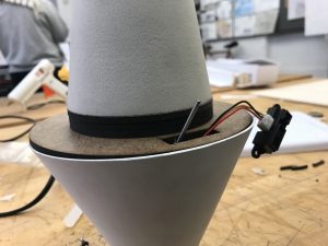
I then turned grey foam on the lathe in order to create the conical form. The inside was carved out using the lathe as well. I had to plan out the form ahead of time so the glass form would be a snug fit and so the taper is proportional to the form. The bottom circle was then measured so the laser cut aperture would fit on the base. Luckily the pins fit well into the foam and helped to keep everything snug. Although the initial plan was to turn the bottom form that would hold the Arduino, servo and battery, I ended up vacuum forming a plastic into a conical shape. This material is easy and flexible to work with, and allows me to reopen the casing if the mechanism stopped working for some reason. 


I also needed to plan for an area where the sand could fall without getting to the Arduino or servo. The proved to be practically impossible because I still needed holes for the IR sensor and servo to access higher pieces. I also had to test out many ways and materials so the servo could access the aperture. I ended up using string to connect the two because it had strength and tension while being flexible to move through snug areas of the mechanism. Unfortunately at the end of the day the servo was still not strong enough. In the future I would find a way to distribute the weight of the glass more on the borders of the aperture so the joints would not have as much difficulty moving. I also would try to use larger grains of sand, maybe even ball bearings of some sort so there’s no chance the particle would interrupt the mechanics. Now that I have a better understanding of the overall necessary mechanics, I would want to iterate on the form to it it more conducive to standing and laying down (and not look like it would be dangerously knocked over and break).


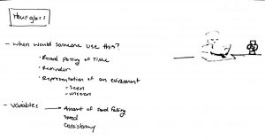
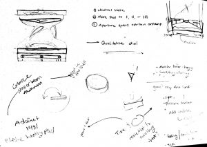
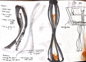
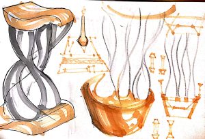
Sketching and Planning: assignment-08-hourglass-sketches-brennan


gloves that control light in an environment

My project was to create corresponding colored gloves to alter light in an environment. Initially I wanted to make something large scale where a room could detect what color clothing you are wearing and adapt accordingly. Unfortunately due to time a feasibility I had to scale down the project. I went through trial and error to incorporate a phillips hue and a particle photon but after much chagrin I had to use a RGB LED strip. Each of the gloves will trigger the lights to change to what ever color the glove is. I used imbedded RFID tags in the gloves.

In action- https://youtu.be/x_YhVYIV59Y

code- https://drive.google.com/drive/folders/1P2NzUPkYD8tC-s_dE_-TWkOaBE09McPA?usp=sharing

Final Crit- Noel Lau

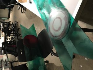
My final project is a cosplay prop from the game Transistor, that uses phys comp fundamentals to bring the prop closer to functions/behaviors in its original work, enhance static features, and bring others to engage with the great works that these props come from.

https://drive.google.com/open?id=1iKilGAet8-1_XHfDLTWK0RPx5Jyya3yF

The first stage was focused on code and learning more about using physical computing components like transistors and capacitors to deliver consistent power to the circuit and read noisy signals. High pass filter methods were used to find the most effective way to read and pulse the LED with. Different conditional loops and commands such as “return”, “goto’ and “switchCase” were also explored to achieve the conditional cases I wanted to program for:

Corrupt Mode: When the sword is lowered from the stand, sword point touches the group and pressed a momentary switch down. The switch reads LOW because the circuit moves voltage from 5 V to ground. The switch is connected to a pin and the Arduino executes a command to fade from blue to red LED strip color, and stay within the red state while the button is pressed.

Normal Mode: Pulse in blue light while second (auxiliary) momentary switch is also pressed.

Push buttons are used in conjunction with if statements.

Booleans and return functions were considered as ways to control when the pulse sensors was activated and taking in inputs, but a momentary switch was the better option because it was a mechanical switch not dependent on the code for the pulse sensor to avoid reading noise.

Much of the difficulty was with prototyping outside of a breadboard- soldering with large lengths of wire and attaching buttons in the absense of pre-existing holes created a building difficulty. The pulse maker has to be strong through the silver hilt, which was not formerly anticipated. I also had a lot of difficulty with making a pushbutton work that did not have 4 prongs (2 prongs only).

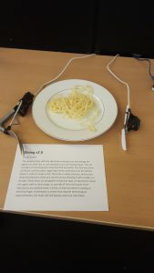
Dining v2.0

This project plays with the idea that was we give our technology the agency to think like us, we also give it our own human flaws.

Therefore I’ve made an ‘IoT-ized’ dining set, featuring a knife and a fork that have been upgraded to improve the user’s dining experience.

The dining set features an eco-friendly knife that you must pump yourself, and a fork that gets a bit nervous when it comes down to stabbing food, and therefore tries to avoid its responsibilities. The fork is plagued by a fear of failure, so it avoids its work rather than attempts to do its job. The knife is afraid to take creative liberties, and so you must instruct it exactly where you want to go.

Demonstration Video:

Code:

Silverware_Code

Making the Fork:

I initially prototyped the fork with a plastic fork, a servo, an arduino, and a tilt sensor. I used a straw to provide resistance, cutting the fork in half and allowing the servo to pull on a string that moved the fork down on command.

I found some springs, and found the motion to be more organic, making it seem as though the fork had life of its own. For the show, I used an Arduino Pro Mini and soldered it to a tilt sensor and to a servo attached to a larger metal fork. By connecting a spring between a cut off fork head and the fork base, and attaching this spring to the servo, I could cause the same motion as the prototype and move the fork.

Making the Knife:

I 3D printed a gearbox for a servo that translated rotational to linear motion. (STL files here)

Then I soldered together an Arduino Pro Mini, a 100k ohm sliding potentiometer, and a servo, and mapped inputs from the pot to rotation (and thus linear motion) from the servo. I split a knife in half and attached it to the end of the linear actuator and the handle to its base.

For both of the utensils, I molded a handle out of InstaMorph, and used it to hide the electronics of the devices. I then wrapped that in electrical tape, mimicking the way sensitive electronics are packaged in devices (for example, batteries or ICs), as a way to highlight the difference between how ‘techy’ devices are constructed versus how the target audience perceives them.

I had also worked on the gearbox for a jigsaw knife (a knife that moves in a similar way to a jigsaw blade), as an example of an overenthusiastic and unnecessary device, but had trouble attaching a motor to the gearbox.

I used this gearbox, and laser cut a baseplate to attach to my motor. I also made a D-shaft to Hex shaft couple out of acrylic, so that the motor shaft would nicely fit into the gearbox assembly, but the motor managed to break through the acrylic due to not being aligned properly when drying. Unfortunately I did not realize the repeated cause for stalling was due to misalignment, and when I tried to glue it again in the correct alignment, it dry a little bit off center.

Bryt 3.0 – An Endless Melody – Final Project

For my final project, I explored music visualization with the arduino with LEDs and mirrors to create unique visual effects. My project has the ability to visualize music on the go through a 3.5 mm audio jack.

******VIDEO IS NAMED: PLAY_ME.MOV*****

https://drive.google.com/drive/folders/1vrhpKTf6-6S3frgSOLTRx7zvACegf1nk?usp=sharing

About:

For my final project, I was really interested in music visualization and sound representation so I decided to build an Arduino-controlled LED music visualizer. I got most of my inspiration from the lights in the Hunt library’s stairwell but wanted to make something different.

So I made a light-up infinity mirror from clear acrylic, an LED strip, a 2-way mirror film, and some super-reflective mirror sheets. The lights surrounding the mirror are RGB, fully controlled with the Arduino. The flashing and color changing of the lights correspond to the music in real time.

In order to get music visualization working, I used a microphone that listens to songs played from the speakers and interprets when the bass is running. From then, I just programmed the Arduinos to change the colors of the LEDs depending of the music.

Final Crit: Children’s Fish Tank


For my final version of this project, I focused more on creating a cleaner final product than I had in past projects  — mainly, I wanted to hide all of the wires and mess.

**Also, I unfortunately couldn’t devise a way to bring my fish tank to campus without potentially killing my fish (which I’d rather not do), so I had to improvise with the vase and jello/Swedish Fish that you see above (this also really hindered me in creating the feeding-contraption, since the vase I used is rather narrow-necked).

gnolan Arduino code


depth mirror: final

Overview:

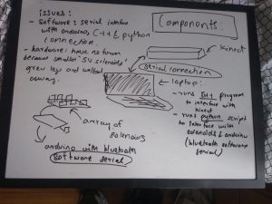
I intended to create an 2D array of solenoids that would respond to changes in depth input through a kinect. It would essentially reflect the depth in the image captured by the kinect. However, I found it very difficult to take input from the kinect and send this data to the arduino simultaneously, so instead I first record a history of depth data from the kinect, and then send it to the arduino via bluetooth, which it then uses to move the solenoids.

video showing this process: https://www.youtube.com/watch?v=fpj6dSkBT7g


Hardware and form:

I created CAD models (in the files attached with this submission), which consisted of three acrylic tiles per solenoid. The two below would have had holes in them to allow the solenoid to move. However, the 5V solenoids I had planned using grew legs and walked away, and this design was inapplicable to the 7V solenoids I ended up using.  (the brainstorming process and design is attached with this submission)

Circuitry:

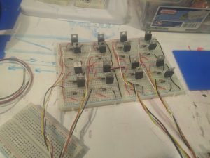
circuit board I made for 4×4 array of 5V solenoids:

finished  2×3 array of 7V solenoids I was forced to use:


Issues I faced:

  • I spent a lot of time trying to figure out how to get depth values from the kinect. I also had a lot of issues with serial connection between my laptop (mac)and the arduino. I finally somewhat resolved this by using software serial with bluetooth. However, as previously mentioned, I had to write another script in python to send the data across the serial connection.
  • I was scavenge for and use 7V solenoids instead of the 5V ones as I had initially planned. This took additional time and configuring.

Acknowledgements:

I would like to thank ideate for providing me with the parts, Akshat Prakash for helping me with the software serial, and Bolaji Banakole for giving me his spare arduino when I fried mine.

link for other documentation, code and CAD files: https://drive.google.com/file/d/13e1UmHgjkUIJSzP44gxqSoUB4iE-ZnXS/view?usp=sharing