Final Crit: Gaurav Balakrishnan

Confused Keyboard 

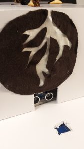
My initial project idea was to just make an instrument that makes people think by being not unlike what people expect. I decided to make a keyboard which looked exactly like a functioning proper keyboard but emitted noise that were slightly off. While the major idea remains the same, I noticed that this would be a very interesting model to mimic very real occurrences of things and people having perfect external appearances but functioning in confusing ways. The keyboard I have finally made is very confused most of the time, playing notes with frequencies slightly off, with tones that are varied, with different and dynamically varying magnitudes. All of this happens without any apparent pattern. However, every so often there is a period of lucidness that can be experienced where the keyboard plays exactly like one would expect. To someone who reads and learns about neurodegenerative diseases, this is a very relatable phenomena.

Components:

An old Yamaha Keyboard
Conductive Copper Foil Tape – Switches
8 ohm Speaker
Wire
10k and 15k ohm Resistors
Arduino Teensy
Class D Amplifier

Iterations

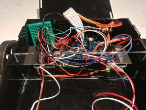
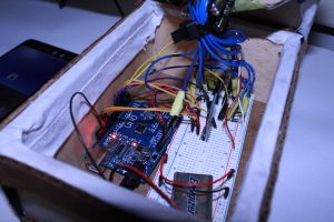
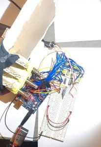
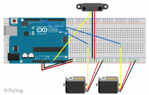
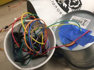
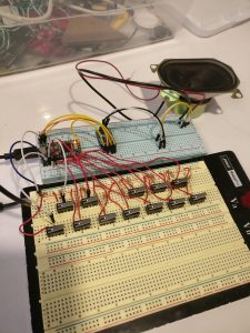
The first draft of this project was conducted with just a couple of breadboards, lever switches, and an Arduino Teensy using the DAC to output waveforms. A code was implemented to dynamicallyh randomize the kind of notes played on each key to show a proof of concept of how the project would work. The image below shows what the circuit looks like.
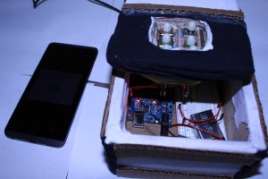
The Final Project 

I decided to try and obtain an actual keyboard to use as a shell and the form for my project. I had two options on how to move forward with it – 1. to access the key reads using the circuits that exist on the keyboard and, 2. to completely rip out all the electronics and implement simply design switches to read using the Teensy. The latter option was selected because it proved to be slightly complicated to figure out the wiring of the keyboard’s electronics. Also, I decided to implement only an octave worth of keys but focus more on the software of the sounds generated by the keyboard. A limitation of the Teensy is also the number of inputs.

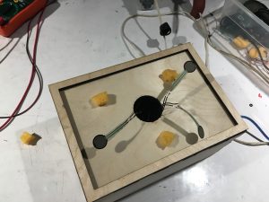
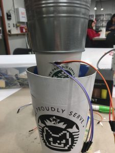
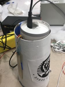
The switches were implemented using Copper Foil tape applied on the keys and in a power line running in the bottom where the keys would make contact as seen in the image below.

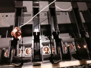
A challenge I ran into was on understanding how to make these switches function in a more reliable manner. I found that reinforcing the foil by applying multiple layers was really helpful.

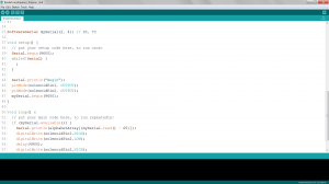
The code is uploaded here. I think it was really interesting to use a DAC to produce waveforms and directly manipulate them to create various effects.

The video is here!

Bolaji Bankole: Final Project

The concept that I set out to convey with my project was distractions and apathy preventing you from achieving what you want/need.

I set about doing this by creating a robot that would meander towards various targets, and you can interfere and distract it along the way. In the end there is some overly interesting behavior, but for the most part it works.

The bot was controlled by a raspberry pi using openCV, and each target had an arduino pro mini with a neopixel and an IR range sensor.

While it mostly worked, there were still a couple of issues that I ran into. The internals of the bot are a mess:

With most of the space allocated for a battery that I’m still having power regulation issues with, so it may remain tethered to a power supply.

video 1

video 2

video 3

Assignment 8: Final Crit on “Draw Your Music” (SooJin Sohn)

DRAW YOUR MUSIC

My final project, in short, lets a webcam to scan and utilize a drawn image from a user, then output it into audio.

Description

Specifically, this project connects with both Arduino and Processing, which activates a webcam to color track the color of a red laser pointer, locate its coordinates within the camera vision range, and translate that into audio ranging from 100Hz to 500Hz. The audio plays on a real-time basis, through a 8-ohm 12-watt speaker. Finally, the power is sourced from my laptop.

Major Changes

Initially, the plan was to have a usb web camera to make a screencap of a fully colored, hand-drawn image, then auralize it using Arduino’s pitch files. I have been spending the past 3 weeks to code 5 different

The biggest challenge and the problem was to merge all codes into one, where captured webcam image data had to all be converted from 2d arrays into bytes. Audio data was hard to manipulate with byte type data communicated through Processing.

Having to realize very late, I decided to simply the idea of screen capturing and analyzing web camera monitors. Thankfully, as I was simplifying the codes I had, I also learned that I could make a more interesting form of interaction. Specifically, I ended up creating a semi-tangibly interactive object, where the user shoots laser beams to interact with the machine, using a laser pointer instead of his/her hands. This was also funny since, this final format was rather very close to my very initial final project idea, where I was attempting to make a theremin-like guitar, that used a laser as a main playing tool.

Reflection + Future Plans

After finishing project, I am now having hopeful thoughts about actualizing my very initial final project idea of making a laser-guitar. I would use some slick-colored acrylic boards to cut an electric guitar, with a translucent white acrylic, interactive tracepad attached in the middle instead of 6 strings. I would 3d print, or laser cut a guitar pick that would function as a laser pointer on its own. Lastly, I would change my selection of web camera, where I can manually fix its focus setting and vision range. ( this will ultimately have me achieve a design where the webcam can still be located closer to the interaction panel)

Documentation on Google Drive(Code/Pictures/Video): https://drive.google.com/open?id=1_hBXMw25CjPZ_EIG4wJ7HDTKHdAacyU6


BrailleTutor – Final Project – Akshat Prakash

BrailleTutor

Concept

The idea is to help in the adjustment-to-blindness training programs to allow “adults who originally learned to read print but lost their sight later in life” to learn braille.

Components

My braille system consists of a braille pad, that is an Arduino controlled six solenoid pin arrangement that creates one braille letter/number at a time. The system also consists of a companion android app that pairs with the braille pad to conduct lessons for the user to familiarize themselves with braille.

Walkthrough

The app consists of three modes. Learn, Test and Refer.

Learn allows you to learn numbers and alphabets paired with the braille pad. A letter/number is spoken and appears simultaneously on the braille pad.

Test allows you to test how well you have learnt numbers and alphabets. A letter/number appears on the braille pad and the app prompts the user for an answer, then giving feedback.

Refer allows you to refer to the braille representation of any number/alphabet in the English language. The user says a character and it is presented on the braille pad.

With this project, I could achieve harmonic communication between the android app and Arduino and synchronously generate alphabets in conjunction with the corresponding braille translation of the alphabet.

Simple Working:

Final Overview:

Issues and Conclusions

The issues I faced were those related to power, design and over-heating solenoids. I used a 12 V DC adapter to power the solenoids and made their action synchronous to generate the braille character.

All in all, I think this was a very satisfying project. I feel I have learnt enough in this class to take an idea and actually create it. Thank you!

Entire project folder:

https://drive.google.com/drive/folders/1rIW53AoUlIqoe380YHmB_wtATQnuxXon?usp=sharing

Scott Final Project

Initially my idea was to create a text to speech keyboard in order to give the anyone with fingers the ability to speak. I found libraries that worked for this, as well as the speaker and power components  I struggled with the keyboard part of the project. After researching online I thought I would be able to use an old school ps/2 connector keyboard with a library I found but I struggled with making the connection perfect with the pins. So I bought a piece online that would do this for me. When it arrived, I tried to get it to work the same way I saw it done online but finally gave up after some fruitless time debugging as well as seeing a few people online with the same issue (never being able to see power in the keyboard) and no known solution.

So I pivoted to making my own controller with force sensors attached to a spongey material underneath a flexible material that the user could push down in different spots on

Then I was able to use the varying sensor values for when the user pushed down in 7 different spots to get 7 different “keys” from the 3 sensors while still being able to know where the user is pressing. Since the mid point I added volume to the speaker with a LM386 audio amplifier as well replacing the power so the circuit could be plugged directly into a wall outlet.

The last touch which was something I had never done before was lazer cutting the box that I put everything inside of. I from an online box-generating site where I entered the dimensions and it gave me a .svg file. I then used illustrator to add the additional circles I wanted cut in certain walls for the speaker and wiring and export the file to use on the lazer cutter.

download code/fritz: codeAndFritz


Heartbeat Pup

Heartbeat Pup is a soft good built for overly anxious children. It takes in the pulse of its human companion and creates a mirror heartbeat effect through a physical simulation inside the stuffed animal. So, the bear mirrors the heartbeat of its companion child. If the heartbeat is detected to be over a resting heart rate, the animal’s own heartbeat will gradually lower until itself and the child’s heart rate is resting.

The bear becomes a grounding mechanism used to manage anxiety by creating a movement or feeling to anchor its companions awareness back to the environment.

How it works:

The child’s pulse is sensed through the pulse sensor in the Pup’s nose. Based on the readings, the Pup’s heartbeat (created through the movement of a  speaker’s cone as electricity runs through it) will either operate at a gradually lowering rate, or will mirror the child’s heartbeat.

Reflection:

This was a project I’d been thinking about quite a few months. Overall, I’m very happy with the execution, and craft of both the program (coming from a beginner level) and the design. The biggest issue I faced was how to clean and process the values from the sensor to get what I wanted. I was luckily able to find well-documented resources at https://pulsesensor.com/ that worked through the signal processing in an interrupt file that I needed (linked in the program as well).

all files, documentation, and process:

https://cmu.box.com/s/shsr8rlt0hj0uhea9fjsoifbz157zg50


Final Project – Sarika Bajaj

For my final project, I made a responsive worm that normally wiggles around on the ground, but when a person comes too close then will look up at the person.

The main challenges for this project was trying to keep the form factor I wanted it – I really wanted the worm to be lasercut wood but getting the wood to bend at the appropriate angle took a fair amount of testing. I found a solution by using two servos that pull the the wood back and keep it in place. Finally, the aesthetics took a good deal of time to try to cover up the circuitry and motors to make it just look like a worm in a tank.

The circuitry and code in itself was quite simple – an analog IR sensor and two servos that pull at string that actuates the worm. However, I think this was a good strategy because of how many iterations the worm movement took to look somewhat good.

A video of the system working (pre aesthetics):

A fritz of the system:

Code: Worm

Videos of Complete Project:

Final Crit Cathy Fang: Millennialism

Millennialism


As a millennial myself, I feel like our generation is very vulnerable to our obsession and addiction to things. As the world evolves at an exponential rate, our generation tries its hardest to keep up with the changes. But sometimes we lose track of what we really want, which makes us want to hold onto certain things in our lives or follow certain ritual/routine that we believe without which our lives would fall apart.

This piece explores the millennial lifestyle with a focus on coffee, cats, and cat cafes. The enlarged coffee cup is a symbol of the amount of stimulant ,like caffeine, that millennials need to start off a day. The logo is a combination of starbucks logo and the internet-famous nyan cat, a product of the meme culture. The user has to “pet” the cup so that it can change color. This interaction symbolizes how the millennials are enslaved to their obsessions. The cup also looks like floating in the air, which is a symbol of this generation that dreams and always has their minds in the air.

Key Features:

  1. Activate with hot water/beverage
  2. While activated, touch the cup to make the Cat happy (LED changes color)

3. When beverage in the cup is being consumed/leaving the cup, the cup animates

Full Video:

https://drive.google.com/file/d/1Z7xNZy0JsYe7m7_NSSXNuARZIdpRJpfC/view?usp=sharing

Process:
Following my previous post (Assignment 7 rough crit: smart cup), I added the temperature sensor. And instead of trying to use a teensyduino, I decided to make a bigger paper cup that can hold my hardware.

By chance, I found a flower pot from ikea that I could use as the top part of the cup. It was an ideal choice because it can hold liquid and is sensitive to temperature change.

Shoving everything into the cup:

In addition, instead of a traditional potentiometer with a rod, I decided to use a soft potentiometer that I can tape to the side of the cup to change the color of my neopixel. This not only solve the problem of limited space, but also made the user experience more interesting (petting the cup to please the cat).

Lessons learned:

  1. Instead of trying to fit everything into a constrained space, I can change the form to make the hardware fit more naturally and securely.
  2. Before, I have never spent that much time on the form of the project. This time, I took my time to make the paper cup and design the logo using Illustrator, which made the project looked a lot nicer and secure.
  3. If I had more time, I would add sound to enhance the user experience. Right now, all the user feedback relies on the change in color of the neopixel, which is quite limiting. I would also add a proximity sensor to make cups interact with each other to furthermore show the social interaction among millennials.


Go to your Fields: An Interactive Mechanical Flower

video: https://youtu.be/xAO66SjFdWg

My final project is a play on a flower. With this project I wanted to present the idea that living things need human connection just as much as the usual basic essentials for survival. So light and water are replaced by physical closeness and touch: when you come closer or further away, the petals open and close, and “water” travels up the roots when you touch the base. The first part of the title comes from a quote from The Prophet by Kahlil Gibran, which describes how a bee and a flower depend on each other through their interaction.

Components: The open/close motion is controlled by a servo motor attached to each petal by wire. The petals and hinges are laser-cut basswood, the base is foamcore, and the root outline is cotton fabric. The LEDs are controlled by a standalone momentary capacitive touch sensor, and the servo motor is controlled by an ultrasonic distance sensor.

The biggest changes I made from my initial prototype were the petals, the base box, and replacing the linear actuator with lighting of the roots. I chose to replace the upward motion because I thought it wasn’t very graceful, and I felt that representing water with lights would be more effective for my purpose. I had some trouble wiring up NeoPixels, so decided to use regular small LEDs instead. I also had some trouble converting my petal drawing into dxf, but it eventually worked with some help from the Soft Fabrication class.

fritzing and sketch: final_project_NinaPrakash