Zortrax M200: Printing Platform

Remove

Removing the Print Platform

WARNING: HEAT HAZARD
Before removing the print platform, switch the equipment OFF, and unplug the power cable.
Unplug the heatbed cable from the platform. Both big and small connectors need to be unplugged.
Remove the platform by lifting UP and guiding out.

Clean

Cleaning the Print Platform

WARNING: CUTTING HAZARD

Put on the RUBBER GLOVES included in the Zortrax M200 Kit. The kit also includes a sharp-edge spatula. Place the platform onto a secure/steady table-top. With one hand holding the platform in an upright position, (gently) guide the spatula across the platform and AWAY from your body and hand. Remove as much material as possible.

*NOTE: Please notify IDeATe Technical Staff if there is any permanent residue you are unable to remove. DO NOT replace the platform unless it is clean and prepared for the next user.

Replace

Replacing the Print Platform
Open the front panel, put the platform back in the printer and plug the heatbed cable in. Both big and small connectors need to be plugged in.
Plug the power cable in. Turn ON the printer and wait until the plate heats up. Notify IDeATe Technical Staff of any issues when returning your M200 Kit.

Zortrax M200: Start Printing

Overview

1. Equipment Overview
The Zortrax M200 is enclosed with (3) semi-transparent plastic shields. (not pictured) When opening front shield/door, you can access the internal parts & pieces. When the equipment is in operation, this door should remain closed.

Inspection

2. Inspect the Perforated Plate

WARNING: HEAT HAZARD

The perforated plate is mounted (with screws) to a heated build plate that attaches magnetically atop the build platform. Before printing, inspect the perforated plate; make sure the plate is free from large debris and leftover material. It is normal to have leftover material embedded within the perforations. If the perforated print platform is sufficient, continue on to the next step below.

If the perforated print platform requires cleaning, follow the instructions on removing, cleaning and replacing the Zortrax M200: Printing Platform.

Load

3. Load your Print File
Open the front panel and locate the SD card slot. The reader is positioned in the front-right of the machine, above and behind the display interface. Insert your SD Card and close the front panel.

i. Using the rotating control knob, browse to item labeled MODELS on the M200 display. Select this option by pressing the control knob.

ii. In the next menu, a list of [.zcode] files will appear. Scroll to your file and select.

iii. In the final menu, the display lists the selected print file’s details (Material Profile & Est. Print Time) near the bottom. Two options are available from this Menu:

> Select BACK to move to the previous screen.

>Scroll to PRINT: YOUR_FILE_NAME.zcode and select, to begin your print job.

If you select PRINT, the equipment will begin heating the build platform, print head, and the internal environment. Make sure the front panel is shut, and close any sliding doors on the 3D Printer fume hood.

Z-Suite: Slice & Save

Prepare to Print

Prepare to Print: Slicing

Within your Print Settings window, selecting the PREPARE TO PRINT Button will begin preparing your 3D Model for 3D Printing. This process is commonly called ‘slicing’. During which your model is ‘sliced’ every ‘x‘ amount of (inches or millimeters). *Where ‘x‘ = Layer Thickness. This process, determines how support and model material are printed on each layer.

The final on-screen result will provide a print-preview, where model material print zones are indicated in blue, and support structures detailed in white. Additionally, the bottom-most panel in Z-Suite, will provide you with details such as: *Material Profile, *Layer Thickness, *Infill, *Support, Estimated Print Time and Filament Usage.

*These settings are detailed in Z-Suite: Print Settings

Inspection

Inspection *Optional
Z-Suite provides an option to insert PAUSES in your print file. This option is not currently supported with IDeATe (Zortrax) M200’s. However, you can use this option to inspect how your part will print on a layer-by-layer basis. Find and select the PAUSE button from your left menu.
After selecting the PAUSE button, a PAUSE menu will expand from the left. Near the top of the menu, an adjustable bar (indicating print progress) allows you to scroll through the print; from layer #1 (0%) to the final, top-most layer (100%). Although this is not a required step, it is interesting nonetheless. Find and select the REMOVE ALL button, then collapse/exit the menu by re-selecting the PAUSE button.

Cost Calculator

Cost Calculator *Optional
*Z-Suite provides an option for Cost Calculation. Find and select the CALCULATOR button from the left-hand menu.

After selecting the CALCULATOR button, a CALCULATOR menu will expand from the left. One value should be adjusted, before receiving a proper cost estimation:

**PRINTING MATERIAL: This value represents the total cost of a single spool. For IDeATe (Zortrax) M200 Printers, this value should be set to ’80’.

**Find and select the CALCULATE button to update the TOTAL COST OF PRINT value. This represents the total cost of the print job. In IDeATe, this averages around $0.10/gram of material used.

Find and re-select the CALCULATOR button to exit this menu.

Important Notes:

* As of JAN-17-2017, 3D Printing in IDeATe Print Lab (A5b), on Zortrax M200‘s is provided FREE OF CHARGE.

** Material pricing is based on Purchase Price, Shipping Costs, and average successful vs. failed 3D Print jobs. *You are not charged for failed print jobs.

Save

Save to Print
When you’re ready to print, find and select the SAVE TO PRINT button from the bottom-left of Z-Suite. The (Zortrax) M200 is NOT directly connected to the computer. You will have to save your print file (File format: .zcode) to a memory card. Memory Cards are available for borrowing in IDeATe Lending (A29).
Browse to a file/folder location, and save your file. Once the file is saved to a memory card, eject the card from the computer and transition to the M200 Equipment.

Z-Suite: Advanced Print Settings

Advanced

Advanced Settings
Selecting the ADVANCED SETTINGS button will expand your Print Settings window, and provide you with additional options.

Seam

Seam
SEAM: Each print layer, by default, begins in the same (X,Y) Coordinates as the previous layer. Seam options allow you to maintain this setting, or change it to RANDOM.
Leaving the SEAM option set to NORMAL, retains the default print settings. In the image above, each black square represents a 3D printed layer. The red dots indicate each print-layer’s starting point. This is an example of the default setting, NORMAL.
Changing the SEAM option to RANDOM, modifies each print-layer’s starting point. In the image above, each black square represents a 3D printed layer. The red dots indicate each print-layer’s starting point. This is an example of the RANDOM option.

Infill

Infill: Mesh & Shell
Two (2) additional INFILL options are provided in the Advanced Setting Menu, MESH & SHELL.
MESH: Prints the model with 0% infill. The top & bottom (horizontal surfaces) and walls (vertical surfaces) are all printed.

SHELL: Prints the model with 0% infill. The top & bottom (horizontal surfaces) surface layers are also removed. When the SHELL setting is selected, an additional option menu appears directly below:

SPRIAL: Adjusts the seam/starting point of each printed layer. This is described in detail, on the previous tab SEAM. (Recommended)

WALL THICKNESS: Adjusts the wall thickness (in layers). (Recommended 2-3 Layers)

BOTTOM LAYER: Retains and prints the bottom surface layer of your 3D Model. (Recommended)

Offsets

Offsets: Outer Contours & Holes

OFFSETS: These options allow you to increase the wall thickness of any vertical or hole surface geometry.

OUTER CONTOURS: Increases the wall thickness for any vertical surface geometry. The input value will increase the thickness of walls in BOTH directions. This will increase the strength of your print, but also changes the internal & external dimensions of your model.

HOLES: Increases the wall thickness for any circular openings/holes. The input value will increase the thickness of walls in BOTH directions. This will increase the strength of your print, but also changes the internal & external dimensions of the hole(s).


Smart Bridges

Smart Bridges
SMART BRIDGES: Enable this option if you wish to print an object with small holes. This will eliminate any printing of support structures within these holes. With this option enabled, removing the support structure within the hole(s) is not necessary. This option is recommended for Models that include hole(s) that are less-than or equal-to 8mm in diameter.

Bottom Layers

Bottom Layers
BOTTOM LAYERS: Increases the thickness of your model’s bottom-most surface. This increases the strength on the bottom of your printed model, which is helpful when removing the part from: a) the printing platform & b) any base level supports.

Z-Suite: Print Settings

Print

Print
If your model is ready to be printed, click “Print.”
 This will expand a side window, allowing you to adjust some basic print settings and preferences for your 3D Print.

Profile

Profile
The PROFILE drop-down option, allows you to select which material is currently loaded. Material selection is limited to Z-ABS only, for safety and technical related concerns. The material will always be pre-loaded by IDeATe Tech Staff. You should always select Z-ABS.

Layer

Layer Thickness

LAYER THICKNESS: this drop-down allows you to choose the height of one printed layer. (0.09mm/0.14mm/0.19mm/0.29mm/0.39mm) Your material selection may affect the available selection choices.

a. Finer layers (0.09mm/0.14mm) = Better surface quality + increased printing time + increased material usage. This is recommended for parts that are intricate/highly-detailed/organic/curvilinear.

b. Average Layers (0.14mm/0.19mm) = Average surface quality + average printing time + average material usage. These settings work well for most shapes and forms.

c. Thicker layers (0.29mm/0.39mm) = Less surface quality + decreased printing time + decreased material usage. These settings are recommended if your part is simple/rectilinear/square. You can also use these settings if your part is a first-stage prototype, or if you’re in a rush!

Quality

Quality

QUALITY: This drop-down option allows you to adjust the speed and quality of the 3D Print.

High Quality = decreased speed + increased code output + increased print time. This is recommended for organic or curvilinear shapes.

Normal Quality = average speed + average code output + average print time. This will work well for any form.

Infill

Infill

INFILL: Allows you to adjust how the interior of your model is printed. *See the image below and continue reading for extended description.


Maximum = High strength + increased print time + increased material usage. Use these settings if your part requires strength and durability; or if you plan on drilling/screwing screws or bolts into the part.

High = Average strength + average print time + average material usage. Use these settings if your part requires average strength; or if you plan on sanding the part afterward.

Medium = Sufficient strength + lower print time + lower material usage. Use these settings if your part is for show, study, or research.

Low = Minimal strength + minimal print time + minimal material usage. Use these settings if the interior of your object or strength doesn’t matter; or if you’re in a rush!

Support

Support
SUPPORT: Allows you to select the angle at which support structures are generated for over-hanging or undercut geometry. If your 3D Model includes over-hangs or undercuts; we’ll have to define when the 3D Printer creates support structures to support these features. By default, this option is set to 20 Degrees. This setting is safe as it provides extensive supports for your model.

For instance, a support setting of 40 Degrees would print support structures for overhanging geometry that is greater-than or equal-to 40 Degrees. An example is provided in the image above.

Lower Support Setting Values = increased print time + increased material usage + increased success + increased post-processing time (removal/clipping of support material from final model)

As a second example, a support setting of 80 Degrees would print support structures for overhanging geometry that is greater-than or equal-to 80 Degrees. An example is provided in the image above. This setting would provide limited support for over-hanging structures, and the likelihood your model will print successfully is minimal.

Higher Support Setting Values = decreased print time + decreased material usage + decreased success + decreased post-processing time (removal/clipping of support material from final model)

SUPPORT LITE: Choose this option to generate the support structure without the outer perimeter. Support Lite consumes less material, is easier to remove, and decreases print time. However, this option can cause problems with complicated Support structures.

Fan

Fan Speed
FAN SPEED: Should be set to Auto.

Z-Suite: Interface & Tools

Views

Views
Click “Select View” to quickly select the view of the model.

Move

Move
Click “Move Object” icon to move the model in the workspace. You can move the model by editing X and Y parameters or click and drag the selected model.

Rotate

Rotate
With “Rotate Object” option you can rotate a model in the workspace in three directions. You can rotate the model by adding an angle or clicking and dragging the selected model. Choose one of the three axes: X, Y or Z to decide in which direction you want to rotate the model.

Resize

Resize
Click “Resize Object” icon to scale the model. You can resize the model by changing the parameters in the table or by using the click and drag option. If you want to enlarge your model in all axes click and secure the padlock icon. With an unsecured padlock you can change the parameters independently of one another

Copy/Delete

Copy or Delete
To copy a model, select an object and press CRTL + C keys. Select the model and click “trash” icon or press delete key on your keyboard to delete it.

Split

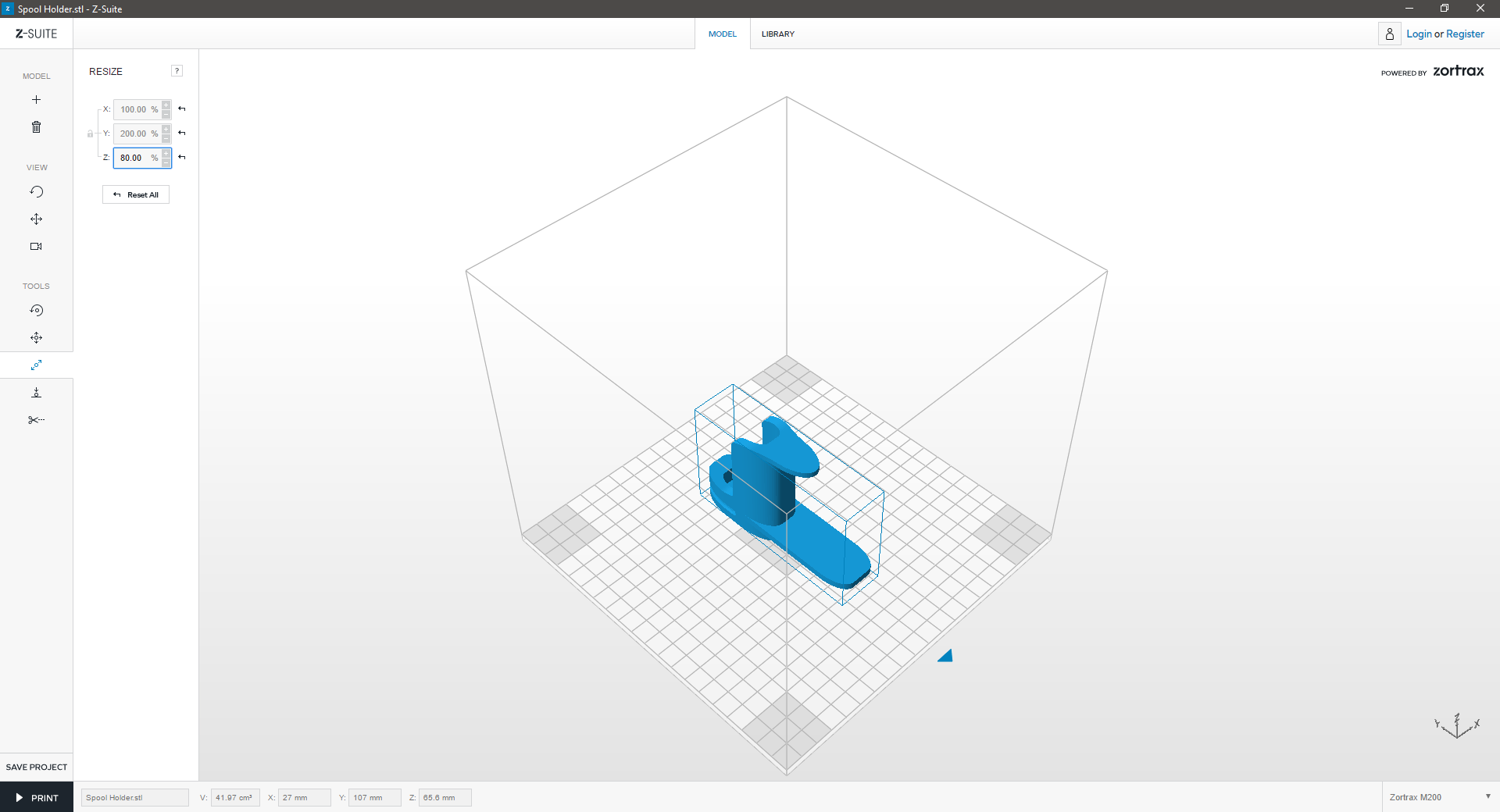
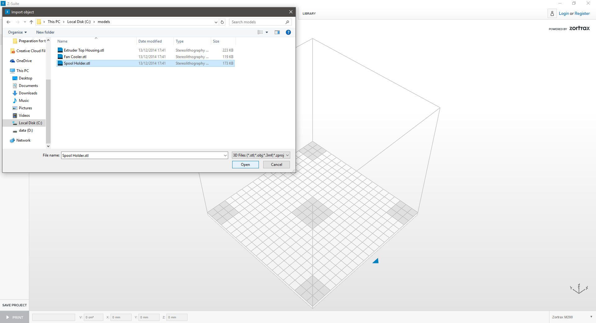
Is your model too large? Z-Suite can split your model into multiple, smaller print-jobs that fit on the print platform:
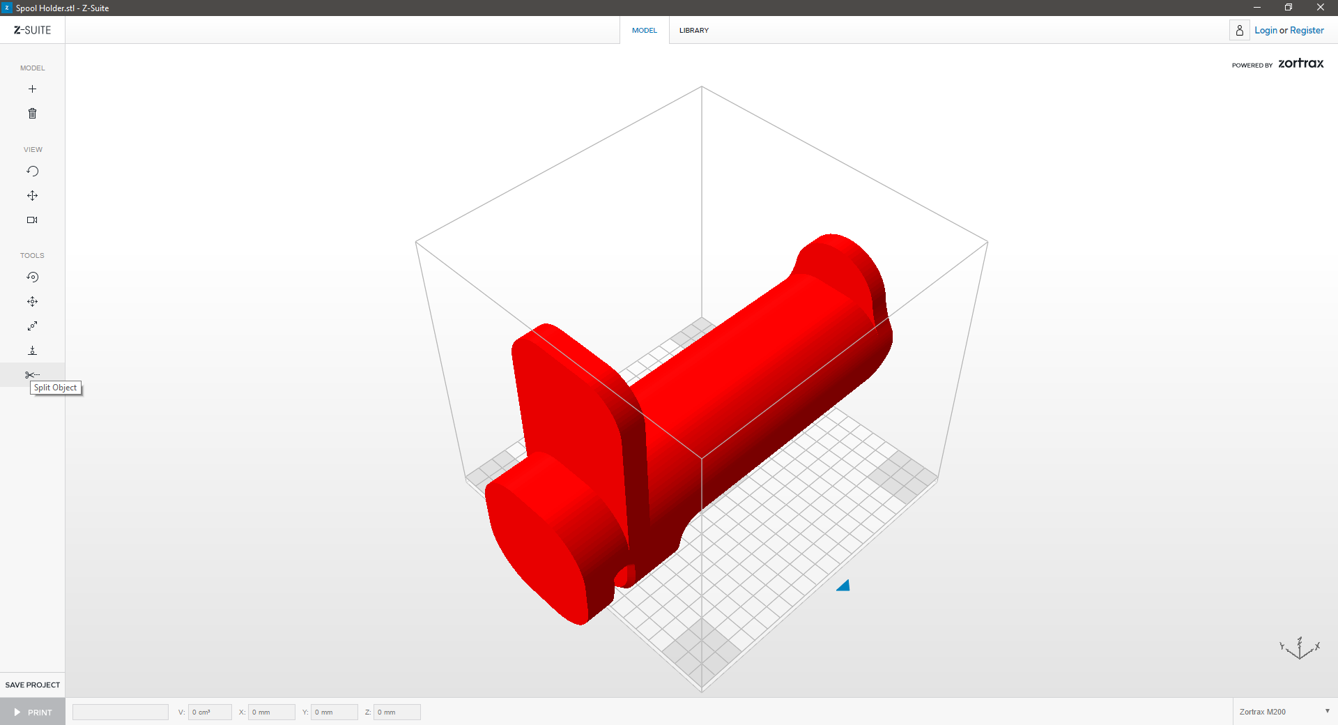

1. Split
Click “Split” icon to split the model.
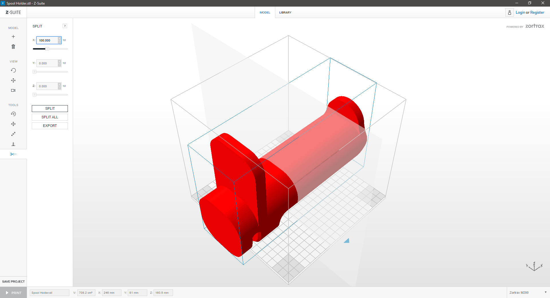
 

2. Cutting Plane
Choose the position of the cutting plane. You can change the parameters manually or adjust the slider and click “Split” or ”Split All.” Each separate part can be saved by clicking “Export”.
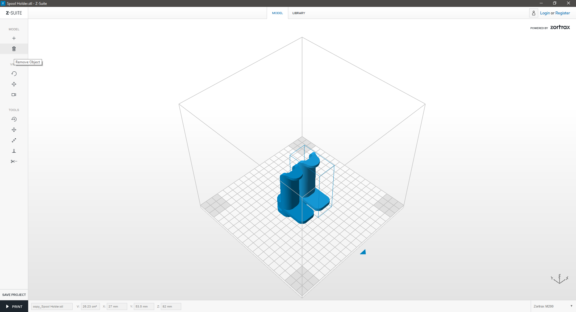
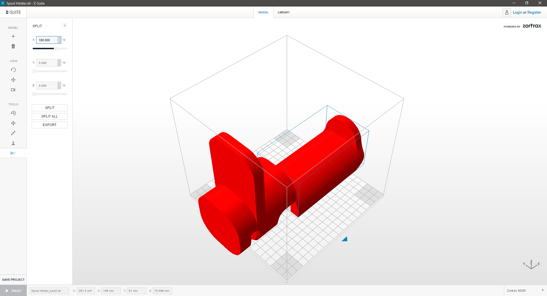
 

3. Arrange
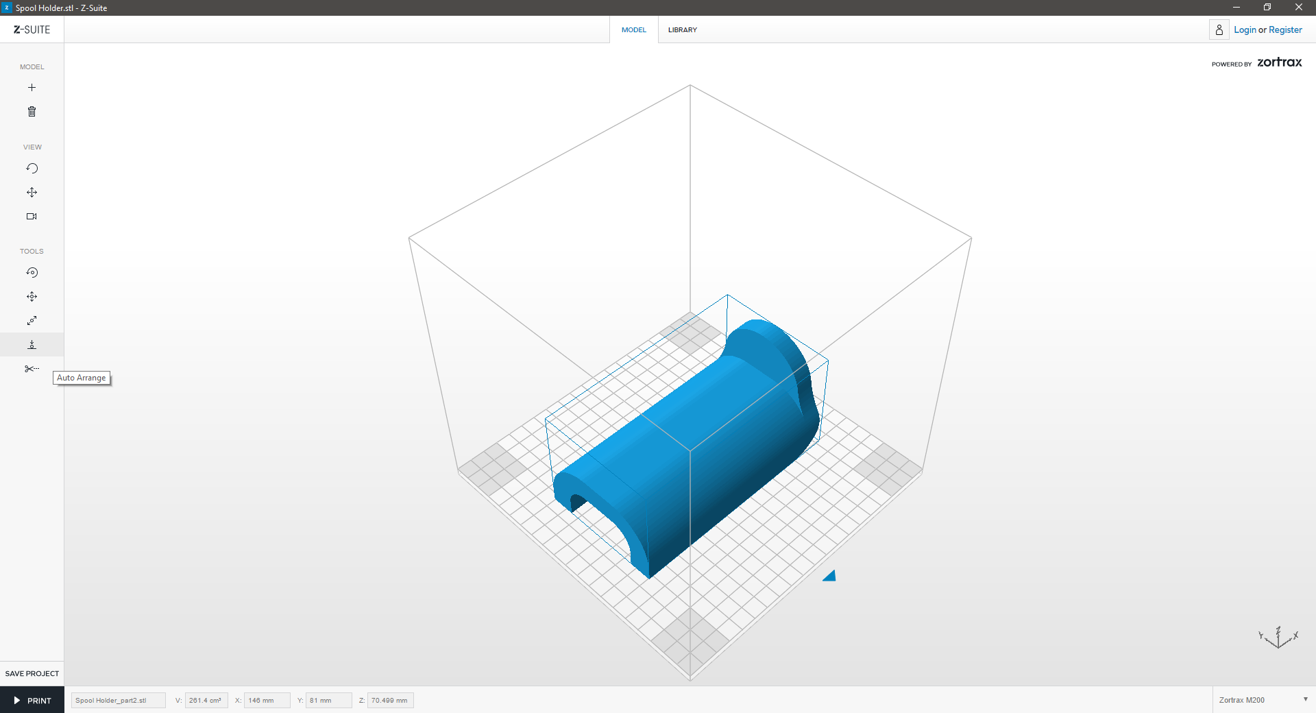
Delete one part of the model and “Auto Arrange” the other part in the workspace to prepare it for printing.

Arrange

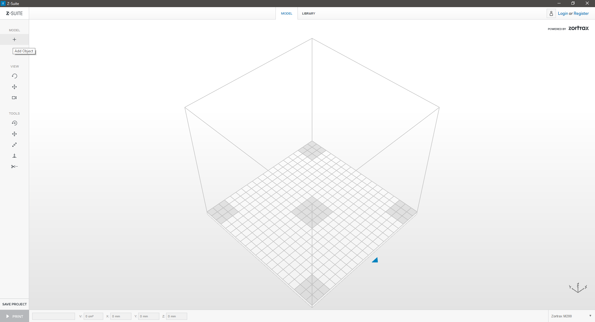
Do you have a multi-part print? If you’re uncertain how to arrange all the items on the print platform, use the Auto Arrange tool:


1. AutoArrange
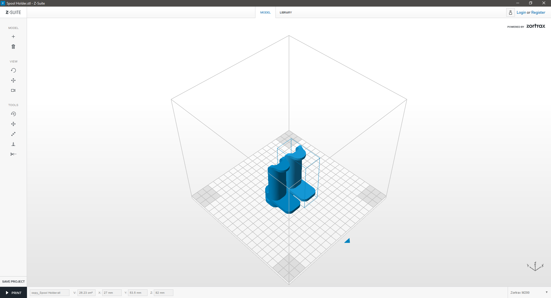
Click on the “Auto arrange” icon in the left menu bar to auto arrange your model in the workspace.


2. RED Geometry
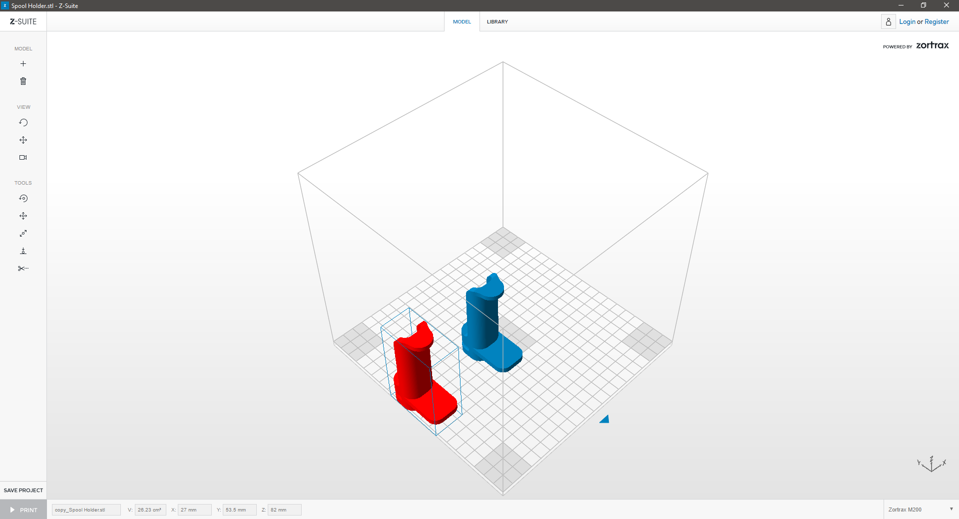
If the model turns red, it means that your model is outside the workspace. Resize or move the model to mould it to the workspace.


3. Orange Geometry
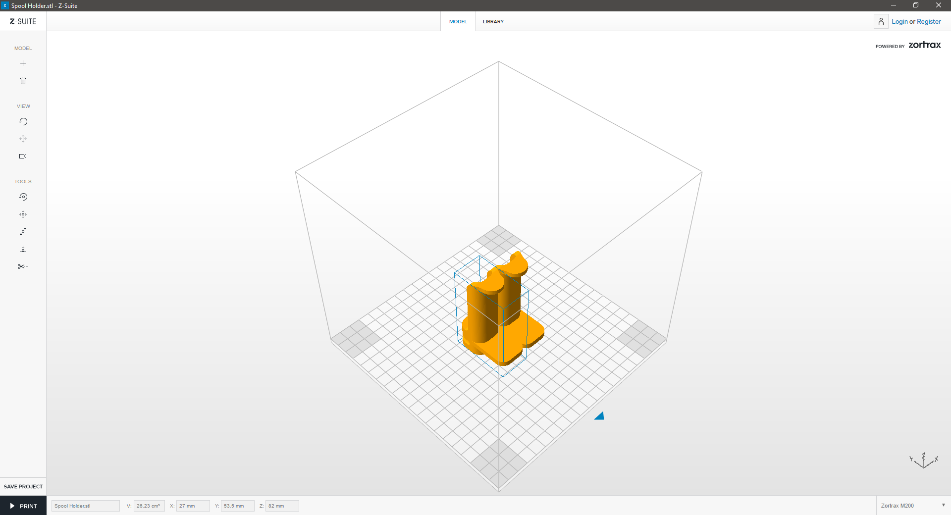
If the model turns orange, it means that a collision between the two models has been detected. You can still prepare them for print. The models will be merged together and printed as a one piece. If you don’t want them to be printed as a one piece, resize or move the models around the workspace.

Z-Suite: Import

Open Z-Suite and upload your file into the workspace:


1. Select System
On the start screen, select the model of your printer which will be used.


2. Upload
Use the “+” icon or the drag-and-drop option to upload a model. You may do so with models saved in an .stl or an .obj format.


3. OPEN
Browse to your file location, select and click OPEN.


4. Prepare
Your model is now within the workspace. To select the model, click the right mouse button. You can save your model at any time by clicking SAVE PROJECT.