Some interesting bits of history mixed in with new technology:
https://www.youtube.com/user/Techmoan/videos
60-223 Fall 2017
Some interesting bits of history mixed in with new technology:
https://www.youtube.com/user/Techmoan/videos
Hi Guys,
Office Hours today 2-6! Come visit me!
-Sydney
Our final project will show that you’ve learned not only the basics of physical computing but that you can create an interactive art project showing off those abilities.
Scale
It should fit on half of the tables we use in A10. If you can make a case for doing a bigger project, we will try and make space. If you are doing a wearable project we’ll need to figure out how people can try it on or if you’ll just demonstrate it while wearing it.
Sound and light levels
Try to keep these low enough to not interfere with conversations or other projects. By the time of the show on Friday we will know enough that we can assign people to tables in a way that minimizes interference.
Project fundamentals
If you have any questions I have office hours from 1-4 on Friday. Jake and Sydney will post their hours in the next few days.
Week 11
Tue, 7 Nov: proposal review, lecture on multiplexers and library 101
Thu, 9 Nov: work day
Week 12
drop pass/fail
Tue, 14 Nov: lecture on problems discovered in week 11, work day
Thu, 16 Nov: work day
Week 13
Tue, 21, Nov: Rough draft/prototype crit, graded
Thu, 23 Nov: TURKEY DAY
Week 14
Tue, 28 Nov: work day
Thu, 30 Nov: work day
Week 15
Tue, 5 Dec: work day
Thu, 7 Dec: Projects DUE, grades will be based on this crit.
Fri, 8 Dec: Final show in Studio for Creative Inquiry, set up at noon, show starts at 1pm
An outline for the proposal, add to it as much as you like. My examples are terse and don’t have any drawings or images, feel free to take a paragraph or two for each element of the outline. If you can’t draw, then use CAD or find images on the Interwebz to illustrate your ideas.
This isn’t about the details of how your project will be implemented, but the concept of what you want it to do and a rough plan for how you’ll work the next few weeks.
Abstract / concept statement
In a paragraph, describe the fundamentals of your entire project.
Example: An electronic piano with that teaches you to play songs on the piano using LEDs, piano keys, and speakers. The LEDs are assigned to keys, when an LED lights up you press the key and hear the correct note. It will have two octaves so it needs 24 keys and 24 LEDs. Maybe it can keep score and grade how well you perform.
Hardware
The rough list of things you’ll need to do this project. “I don’t know” is an ok answer for some components.
Example: Piano keys x 24, LEDs x 24, at least one speaker, something to hold all the components together that looks like a piano.
Software
What software will you need? Again, a high level description is fine, so is “I don’t know” for some of the elements.
Example: I’ll need software that can read a music score, display the score as LEDs over the piano keys, read the piano keys, then make sound on the speakers. I need to be able to change the music score and keep track of someone’s performance ability.
Order of construction and testing
This is a critical part of your proposal. Stop and ask yourself: “In what order will I build things over the next few weeks?” You can’t do the entire project at once — divide it in to discrete parts that you know you can complete and test.
Example:
This is an awesome science project out of Europe!
It’s the future, today
http://www.instructables.com/id/Acoustic-Levitator/
Video discovery by Gaurav
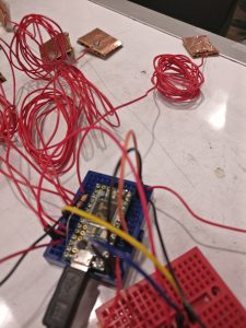
I decided to make a crude version of a wearable synthesizer where capacitive touch sensors were placed without an obvious order relating to the notes. The idea was to have the user search for the notes often not knowing what the next note would be. I felt like this would lead to some unknown and interesting sounding tunes. Another feature of this system is that the scale that is played varies based on the amount of light in the environment. I envisioned a darker sounding harmonic minor sounder scale when it is night time and a happier major scale when it is day time.
This project used an Arduino Teensy because of it’s ease in creating capacitive touch sensors. I built the capacitive touch sensors using conductive tape made of Cu. A callibrated photodiode is used for measuring the amount of light in the environment.
Set Up
The form of the project is something I definitely needed to give more forethought. The long wires attached to the sensor were harder to incorporate into clothing than I had imagined. I definitely need to get better at envisioning how I want the project to look
Videos:

Screen printing with light up ink…The goal of this project is to create a textile-based interface for music playback, so a person will not need to check their phone for a simple task.
The current form is a foam core model that houses the arduino and other cables. A USB cable processes capacitive input from the printed gesture bar at the bottom to understand a user’s intention. The paper displays visual feedback to indicate the musics state. The video below describes how the technology works.
video: https://drive.google.com/file/d/1EJIESAEm1SMStlUSgDwj8bMH1EtvPG-tGw/view?usp=sharing
code:
https://docs.google.com/a/andrew.cmu.edu/document/d/1ednE3JerYnec_6ge_S1oZaxNwHeQ6SDGRE5l3FL0DEA/edit?usp=sharing
The first thing I had for this project was a series of shrieking speakers that shrieked harmonically, the frequencies of which could be raised and lowered with a potentiometer.
I wanted to make a series of tentacles that vacuum pumps would undulate uncomfortably, and would scream when touched. However, depression was kicking my ass this week and I could barely keep lucid enough to make sense of code at all. I ended up working with a heart rate monitor because it required less extra steps to make something spooky, because awareness of your own blood running through you is inherently creepy.
I wanted to have a wide variety of subtle atmospheric effects surrounding an alter-like sculpture, which would raise to a more anxiety inducing crescendo if they were reading someone’s rapid heart-rate. Blinking LED eyes were to be a single element, not the central ones, but this is what I ended up with.
This is the final project of the Spooky Scary Mask, if you want to review the first part of the prototyping (the distance detector, how to play sound), please click here.
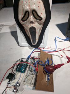
This part of the spooky scary mask, the main focus is how to work with the solinoid/fluid pumps and the mechanical part of the project. The main goal for the mechanical part is to make the fake blook flush into the mask, to create the bloody scary effect.
Here is the fritzing sketch for this somewhat-working demo, whichi is not a whole lot more complicated than the previous one:
Here is the code, not much have changed from prototype part 1:
//JeanZhang_yihanz
//The Bloody Scary Mask - Part 1
//This code contains code and resources from this webpage:
//http://randomnerdtutorials.com/complete-guide-for-ultrasonic-sensor-hc-sr04/


//Set up the pins
const int trigPin = 11; //Trig - green Jumper - digital
const int echoPin = 12; //Echo - yellow Jumper - pwm
const int soundPin = 5;

const int solinoid1 = 9;
const int solinoid2 = 8;

long duration, cm, inches;


//This is the function for a spooky sound (doesn't have to be exactly like this)
void scarySound() {
 for (int i = 100; i < 1000 ; i+= 20) {
 Serial.println(i);
 tone(soundPin, i);
 delay(50);
 }
 for (int i = 1000; i > 100; i-=20) {
 Serial.println(i);
 tone(soundPin, i);
 delay(50);
 }
 noTone(soundPin); // stop the sound after the trigger
}


void setup() {
 //Serial Port begin
 Serial.begin (9600);

 //Define inputs and outputs
 pinMode(trigPin, OUTPUT);
 pinMode(echoPin, INPUT);
 pinMode(soundPin, OUTPUT);
 pinMode(solinoid1, OUTPUT);
 pinMode(solinoid2, OUTPUT);
}

void loop()
{
 digitalWrite(solinoid1, LOW);
 digitalWrite(solinoid2, LOW);


 // The sensor is triggered by a HIGH pulse of 10 or more microseconds.
 // Give a short LOW pulse beforehand to ensure a clean HIGH pulse:
 digitalWrite(trigPin, LOW);
 delayMicroseconds(5);
 digitalWrite(trigPin, HIGH);
 delayMicroseconds(10);
 digitalWrite(trigPin, LOW);

 // Read the signal from the sensor: a HIGH pulse whose
 // duration is the time (in microseconds) from the sending
 // of the ping to the reception of its echo off of an object.
 pinMode(echoPin, INPUT);
 duration = pulseIn(echoPin, HIGH);

 // convert the time into a distance
 cm = (duration/2) / 29.1;
 inches = (duration/2) / 74;

 Serial.print(inches);
 Serial.print("in, ");
 Serial.print(cm);
 Serial.print("cm");
 Serial.println();

//if the person is close enough, things will be triggered
 if (cm < 20){
 digitalWrite(solinoid1, HIGH);
 digitalWrite(solinoid2, HIGH);
 scarySound();
 }
 delay(250);
}
Reflection:
The coding and wiring part of the second half is not hard to figure out. However , the mechanical part is really hard to be done. Since I bought the mask from a Halloween store, and this is a part of a kid costume. The bloody “heart” is made for the force that can be applied by human hand. In this case however, the solinoids can’t apply
Video:
https://drive.google.com/file/d/0B0lS0mmjvCWPd1NuczBJTm9RbUk/view?usp=sharing
To reiterate my idea:
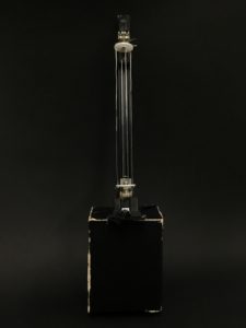
Sound exists as sound wave but is only perceived by us through vibration of objects. In this project, I want to change the way we perceive and manipulate sound by emphasizing on the motion of sound waves.
As a violinist, I feel the music through the position of my fingers. When I first learned how to find the right finger positions to play different notes, my perception of pitch carries a more physical form (location on finger board). I am inspired by this idea and want to present that experience through this project.
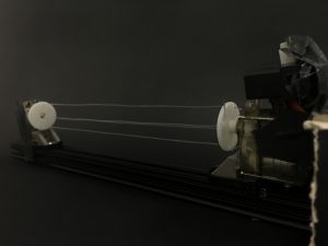
As the user move their hand across the strings, the tensity/deformation of strings varies. The users will then fine tune the instrument by finding the pattern of pitch change with respect to their finger position. The sound is really unstable, which adds emotion and interaction to this instrument.
=====================================
More problems I ran into/Things I fixed:
1. The IR sensor reading was really unstable. I first changed how often I take the data but the reading still fluctuate a lot. So I googled and found that I should add a 100 uF capacitor.
2. Servo almost did not work. After I fixed the IR reading and sound input, I could not start my servo. I played around with the range of servo input and double checked the wiring, and I did not find any error. Then I increased the current and voltage input and suddenly the servo was running. (the arduino god did not give up on me!!)
After prototyping the capactive sensors and the polyphonic function I went about creating an enclosure for the full piece. I lazer cut and engraved a small box to fit in the palm of ones hand, and added a strap for security and comfort. It’s not the most ergonomic thing in the world, but it functions…
I ran into extensive problems with the capacitive sensors and wiring. Hopefully someon can exlpain this to me, but for some reason whenever I used wires longer than about ~6 inches they would begin to trigger from the proximity to the power wire. I then took apart the box and added another slot to run the sensor wires through, this proved also innefective as I ran into the same problem with longer wires. If I had more time I would have set up the whole thing inside the box, but at this point I had already taken it apart several times and was doubtful I could fit everything inside this small of a form factor. I settled for being able to hold the thing, and just not move around too much.
It has a volume control on the breadboard, and you can switch notes and key by changing the pins the wires go into.
I was unable to integrate the 3axis accelerometer for the other hand, but I’m happy with the piece as it is.
Happy to demonstrate in class!
https://drive.google.com/file/d/0By_HygQXfEhJZDRTM2c5UWFmYWc/view?usp=sharing