Emotional Support Flower

Premise

What if you could have an emotional support flower that you don’t have to worry about feeding or accidentally killing it. For this project I was inspired by Chromotherapy, a type of treatment that uses colors to treat diseases. Learn more behind the history and psychology of Chromotherapy here.

There is a lot of research on how to extract emotions based on heart rate and blood pressure data.

Similarly, there is a lot of research on the psychological effects of certain colors.

Project

With all this information in mind, my project creates an emotional support flower that reacts based on your emotions. For example if you are anxious, the flower will start to show calming colors in a soothing pace and pattern. When you do something great, it shows happy colors in an “excited” and “happy” pattern. And in the case that you do something bad, it calls you out on it but in a way that tells you you can do better next time, rather than shame you.

Inputs: heart rate and blood pressure data

Outputs: changing color, pace of changes, and gradient of color changes.

In future iterations, the flower could also incorporate excreting essential oils from it’s stamen. Smells are known to have the most impact on your brain out of all the senses. So having calming oils could really help calm an anxious person, for example.

Proof of Concept

I originally started by mocking the flower up with a 3D pen, but realized that the hardness and stiffness of it was not as soothing of an experience as I was going for. That is when I switched to a softer version made out of dried hot glue. I chose hot glue because it was a quick, low-budget way to get both the translucency and the softness I was looking for.
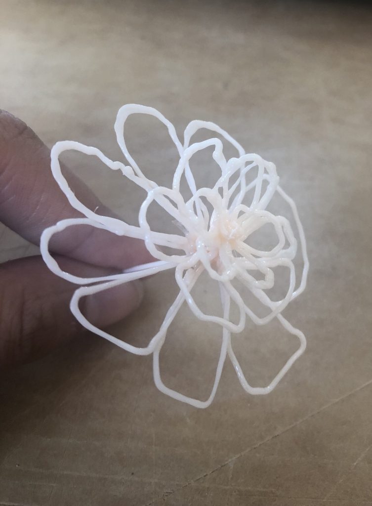
Original Mock Up
Updated Mock Up

Assignment5_Code

Code Inspiration

More Research Links:

color meanings

color psychology in marketing

color psychological association
relationship between heartbeat and emotions

relationship between heartbeat and emotions 2

Time to Get Back To Work!

Problem

I often leave my room to go to the kitchen or answer the door and instead of going back to the work I was doing I get distracted by other things around my house. I wanted some kind of indicator that would alert me more frequently the more time I spent away from my work

I wanted to make something that would get your attention but not alarm you. Additionally, I thought it was important for my device to have a gradual change from a reminder to a more urgent indicator.

The Solution

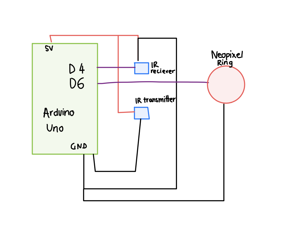
Using an Arduino Uno, IR Break Beam Sensor and a Adafruit NeoPixel Ring. I created a project which pulsates red initially very slowly and as it reaches the 2 minute mark starts to speed up – eventually turning into a flashing light. My hope is that as it flashes more frequently it is more likely to catch the user’s eye – reminding them to go back to work.

Code

Unfortunately, I couldn’t find a Fritzing part for the IR Break Beam sensor. So I made a ‘sketch’ myself 🙂


Link to Video


Assignment 5: Blind Spot Warning System

Problem

How does a vehicle operator gain agency over potential objects in their blindspot? Often the solution is to check all mirrors, but there are very realistic occasions in which this does not work.

Solution

A series of vibrating and tapping motors would allow drivers to tell if there were vehicles or objects in there blindspot. The array of devices would be positioned under the seat and in the seatback, pulsing the left or right side to indicate blindspot object position. Additionally, while parked with the car off, the doorhandle would vibrate if the vehicle sensed incoming objects, such as in the case of a cyclist approaching the driver side door.

Proof of Concept

An ultrasonic sensor would serve as an object detector. When the ultrasonic senses an object in the near vicinity, the device will signal a solenoid motor to tap every few seconds, assuming the “vehicle is running”. If the vehicle is in fact not running, the device will signal the “car handle” dime motors, depending on which side the object appears.

hapticDrivingDemo

assignment_5


Assignment 5: Rain or Shine?

The just in time umbrella indicator

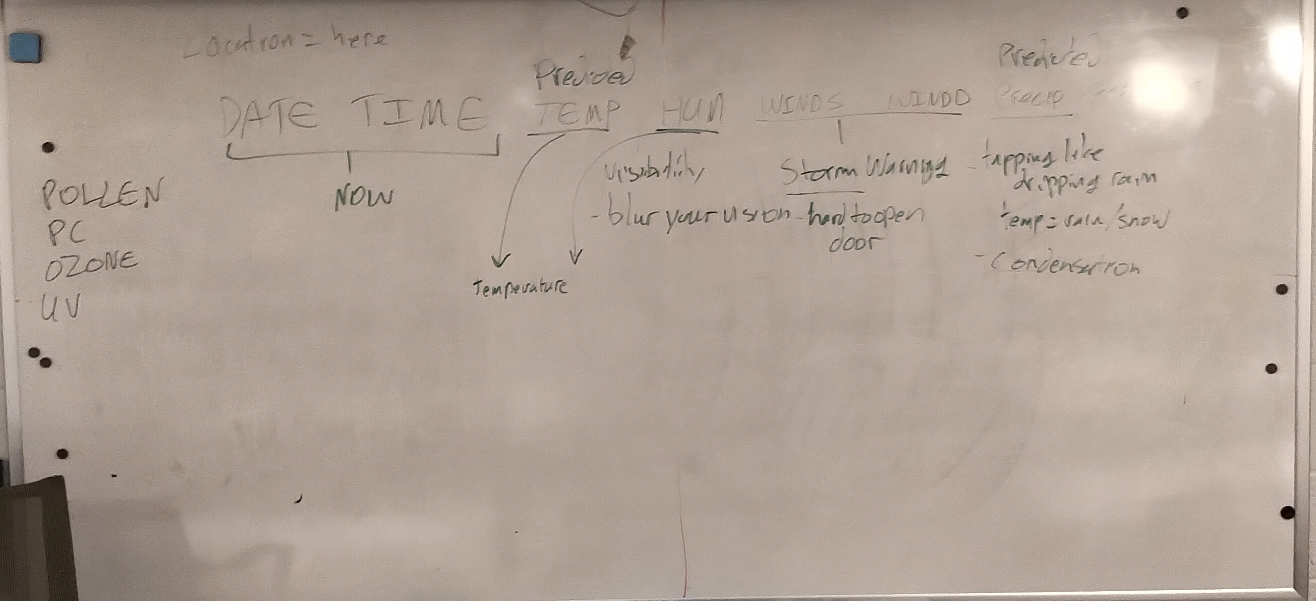
You’re in a hurry on your way out the door for the day. You grab your keys, your wallet, your phone, and head for the door, but then you freeze… is it going to rain today?

Your bag is already stuffed to the max, and you don’t want to have to carry around an umbrella just in case, so you stop, pull out your phone to find the weather app, and look to see what the day has in store for you.

There’s 16 new notifications, and one of them distracts you just long enough for a new one to pop up telling you that you’ve missed your bus before you get a chance to discover that you’ll need that umbrella while you stand out in the rain waiting for the next bus to get you where you’re going 20 minutes late.

What if your stuff knew when you would need it. What if you immediately knew it was going to rain right as you reach for your umbrella, or better yet it pointed you to grab your sunglasses instead.

There is plenty of information available these days, but we always have to go hunting for it in a haystack of apps and notifications.

In the future we can teach our devices (not just our phones and smart devices) to fetch that information for us, and instead of just notifying us, they can take physical action in the real world. Instead of pestering us every time they have new information, or waiting for us to ask for it, they can present it at just the moment it’s needed.

You don’t care if it’s raining until you are about to walk outside, and you shouldn’t stop to check on your way out the door.

The Prototype

To demonstrate the basic idea of this type of physical indicator, a servo motor points at either your sunglasses or your umbrella based upon the message it receives from a weather API like Dark Sky. The response is parsed, and the device is sent a simple string saying either “sunny” or “rainy”. Based on that feedback it points either to the umbrella or the sunglasses.

Here’s a video:

The wiring and code are very simple in this prototype, but to implement the more futuristic versions described above wouldn’t really require much additional wiring or code.

The only pieces required are to embed a haptic motor, micro-controller, battery, and transceiver into the device. Inexpensive controllers like that already exist, but are not yet ubiquitous.

The other half of the equation is a system capable of taking in all of the IoT data in your environment and on your person, and understanding the bigger picture of what combination of triggers should wake up your umbrella just as you’re walking out the door. Smart home devices are getting closer to this every day.

Code + stuff:

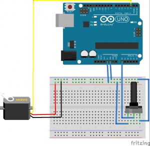
The wiring is straightforward. Just a standard servo connection.

rainorshine.zip

getweather.py.zip

Visualizing Car Speed Through a Kinetic Dashboard Ornament

Problem:

When driving a car, it can be easy to zone out and lose track of one’s speed. The method that current cars use to quantify speed is purely numerical (through a digital display)—an output that doesn’t do a great job in turning one’s speed into a visceral/understandable experience.

Proposed Solution:

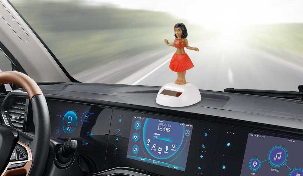
My idea is to express driving speed (while still visually) as a kinetic object placed as a dashboard ornament. I think this would be a fun and intuitive way to display data rather than simply outputting a number.

More specifically, I want to use an accelerometer (represented in this iteration instead as a potentiometer) as an input device; and an oscillating dashboard ornament (powered by a servo motor) that changes oscillating speed in response to vehicle speed.

In the future, it would be interesting if I could make the device smart enough to process speed limit information as well to give the system a value to compare the user’s driving speed to.

Proof of Concept:

Arduino Code and Fritzing Sketch

Assignment 5: Pump Your Breaks

Data Set: Highway Police Locations

2024 Assumptions

  • People are still driving because autonomous vehicle timelines have been pushed back (again)
  • Police departments have become more transparent to assure citizens of intentions (or more people submit data on police locations to Waze)

General Problem: One of the most common sources of frustration and/or stress during road trips is running into a speed trap on the highway. No matter what speed you are going, everyone seems to tense up for split second when they see a police car in the distance. Sudden slow-downs or stops on the highway can be extremely dangerous, especially when other drivers do not slow down accordingly. Is there a way to alert drivers as to law enforcement locations to give them ample time to adjust speed safely?

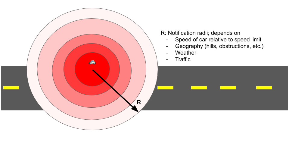
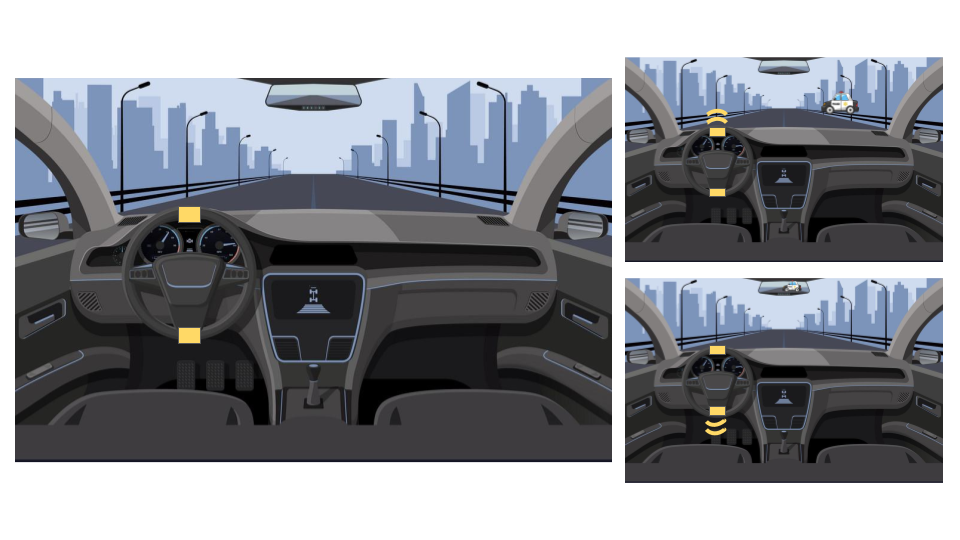
General Solution: Utilizing different sources of data, cars could install haptic feedback systems in steering wheels to alert drivers as to law enforcement locations. When you see a police car, it is often too late to really change your speed, especially safely. This haptic feedback system would take in data sourced from either local police departments (maybe) or crowd-sourced from apps like Waze to determine where police cars are lined up. Based on their locations, your car’s location and speed, the current traffic and weather circumstances and potentially geography of the area, this new gadget would determine a certain distance from the police car that you should begin to adjust your speed in order to avoid getting a ticket and doing so safely. The best feedback for this gadget would be two points of haptic feedback in the wheel. This would allow the driver to still focus on the standard audio and visual pieces of feedback their car already gives them, but a strong buzz on the wheel would be hard to ignore.

Proof of Concept: This prototype uses the following materials:

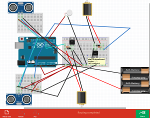
  1. 2 Vibrating Motor Discs: to represent the haptic feedback; one for the top of the wheel to alert driver to police ahead, one for the bottom of the wheel to alert the driver to police behind (see image below)
  2. 2 Ultrasonic sensors: to represent car’s distance from police car (one behind, one ahead)

Video coming tomorrow (Tuesday) (fickle vibration sensors – want to lay them down/tape them down in classroom)

More Thoughts: I wanted to tackle the vibration motors because Jet mentioned it was hard to smooth them/make them less noticeable or shocking to people. I tried a few things and nothing quite did the trick which is why I ended up “coding” the varying distances using patterns not intensity. Also, these vibration sensors are tiny and fickle little pieces of hardware for future reference.

A5_PoliceScanner

Anti-Slouch Machine

Problem:

As people interact more and more with technology, a problem with sedentary lifestyles is the toll it takes on people’s bodies. One way to alleviate these problems is to promote good posture while sitting.

A General Solution:

A device that would sense the angle of a user’s back and give feedback based on its interpretation of the user’s posture.

Proof of Concept:

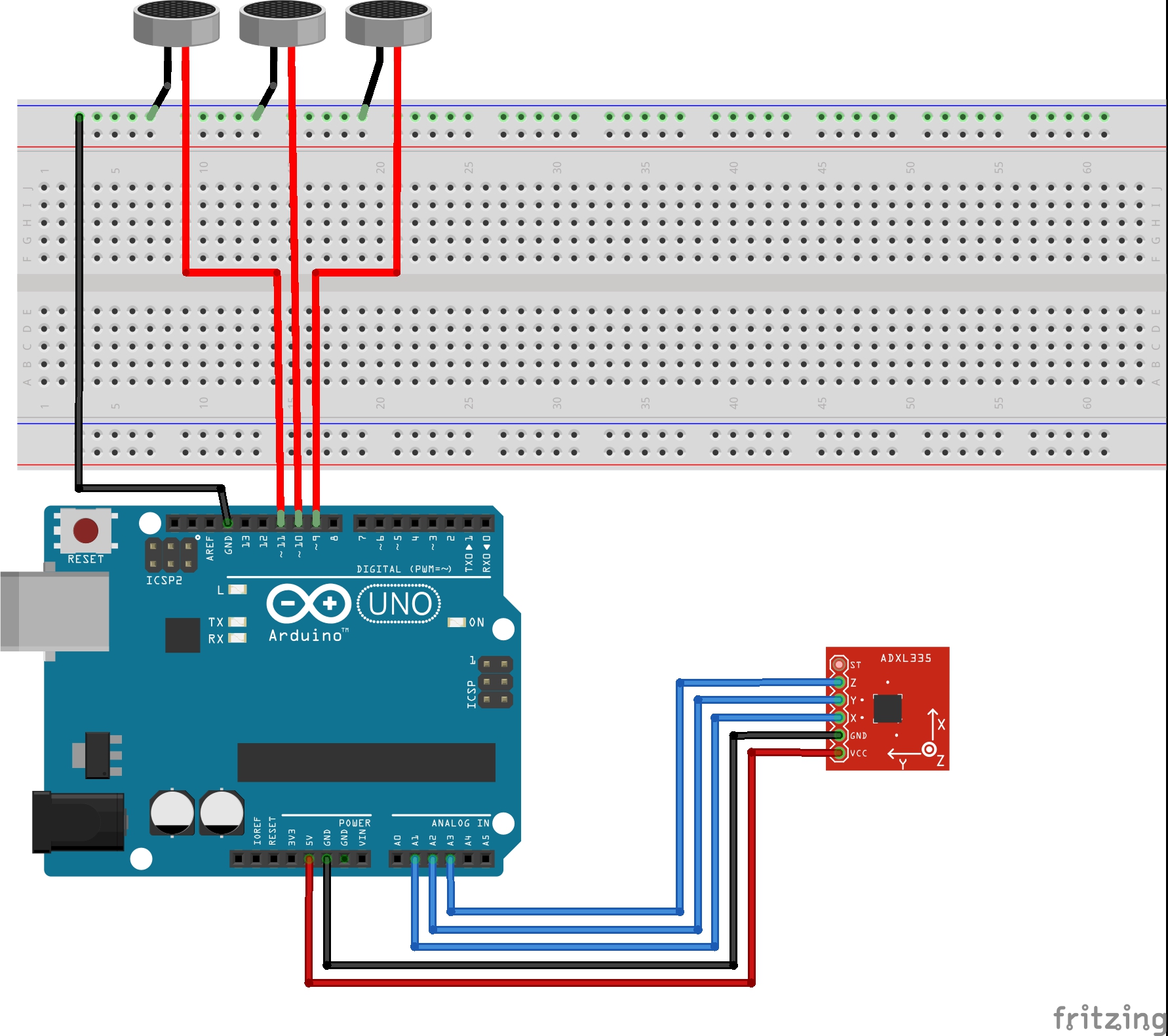
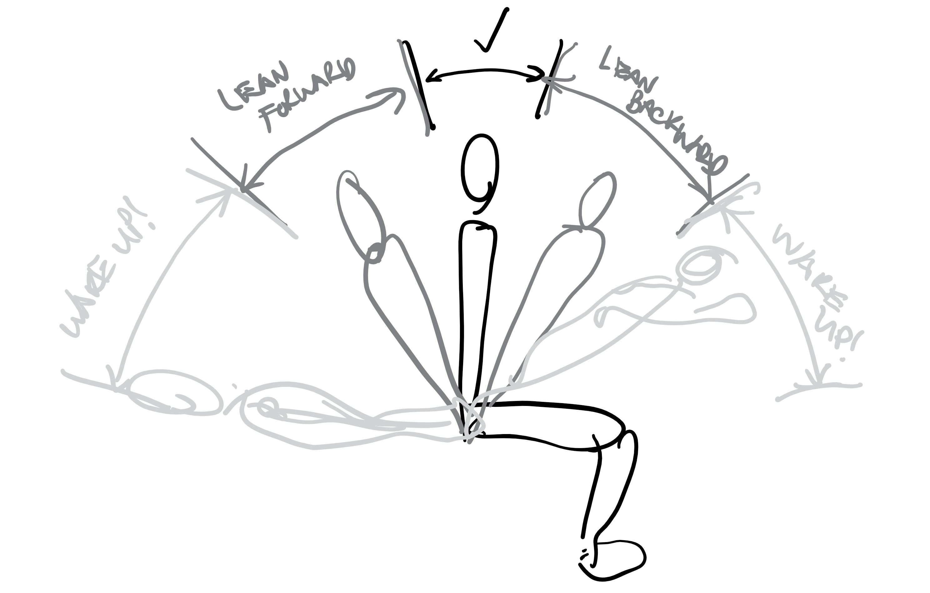
An Arduino with an accelerometer to act as input data to control some transducers which represent a more extensive network of physical actuators.  When the accelerometer senses that the user is sitting up straight, none of the actuators move. When the accelerometer senses that the user is slouching or is leaning too far forward, the vibrations move in sequence to guide the user to lean forward or backward in the correct direction. If the user decides to not correct their posture, the device will eventually get to the point where it will just constantly vibrate unless the user fixes their posture. This occurs for a duration of time until the user’s ‘probation’ period has expired (expires when user doesn’t slouch for a while). When the accelerometer senses that the user is asleep, it vibrates gently, fading from nothing to a softer vibration to wake the user up.

Fritzing Sketch:

The Fritzing sketch shows how the accelerometer is setup to send information into the Arduino as well as how the transducers are connected to the Arduino to receive outputs. The transducers have been represented by microphones, which have similar wiring diagrams. Not pictured, is that the Arduino would have to be connected to a battery source.

Proof of Concept Sketches:

The transducer senses when the user is asleep, slouching, or sitting with good posture and sends a corresponding output to the transducers which vibrate to inform the user of how they are doing.

Proof of Concept Videos:

Demonstration

LED Demonstration

Files:

Assignment_5_Final

Assignment #05 – Feeling the Memories/Photos with Space and People

Problem

Photographs are closely related to our emotions and memories. They remind of associations with places, people, and stories. Technology has made taking and managing photos much easier than before, but there are still some gaps.

One of the most precious resources of the modern household is time, and the effort to take care of all those wonderful photographs defeats their value. (…) Digital cameras change the emphasis, but not the principle. (…) Thus, although we like to look at photographs, we do not like to take the time to do the work required to maintain them and keep them accessible. Donald Norman (Emotional Design, 2003)

Thanks to the smartphone, we can always be accessible to the photos not only in the device but also in the clouds. However, it does not mean that we feel free from those efforts. We actually don’t see the photos that we have taken that much. I tried to think about how can I use tactile feedback for the emotions related to photos.


General Solution

Since photographs are closely associated with places and people, I thought that I could use these data sets.

Scenario #01 – An accidental encounter with my memories here

When I am passing by a location where I visited before and took photos, the phone alerts me with the vibrations in certain patterns and pop-up some related photos. According to the number of photos and/or the emotions related to them (happy, sad, nostalgia, etc), the patterns change.

Scenario #02 – My emotional connections to places

When I am planning to visit somewhere, and finding a place through map application. I can turn on the heatmap layer on the map, which shows the connections between my photos/memories/frequency of visits and locations. Also, when I touch a specific place on the map, I could feel the vibration patterns based on the number of photos/memories/frequency of visits and/or related emotions.

Scenario #03 – Memory reminder with people

I am planning to meet my friends. While texting and arrange a meeting with them (or extracting data from my scheduler), my phone automatically exposes the photos that I have taken with them or that are related to them in some ways, to remind me of the memories and stories with them.


Proof of Concept

To design the tactile signal for these features, I am trying to design vibration patterns. I used Swift and Xcode to use the haptic feedback features of the iPhone X. There are vibration, tactile feedback (success, warning, error), pressed (light, medium, heavy). I tried to design patterns based on them.


Video/Image

Assignment #5 – Icy Roads

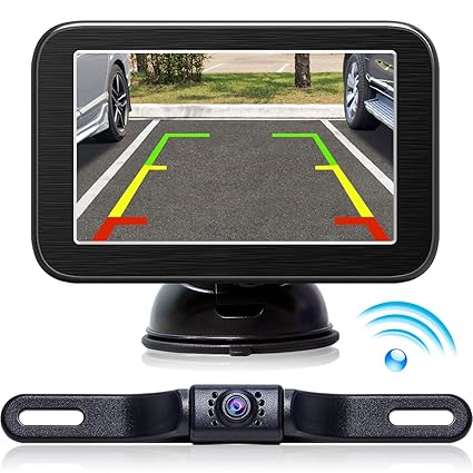
Problem: In contemporary cars, its common for backup cameras to have additional visual aids such as guiding lines and audio feedback such as a dinging that gets quicker the closer you are to an object.  Rarely, there are haptics in the seat as well.  These haptics are often bad, and may even be different based on where you’re sitting in the seat or how thick / how many layers are between you and the seat.  Further, its the same feedback no matter the road conditions, something drivers want to be aware of.

Image result for backup camera

The Solution: First, the audio dinging does not really communicate exactly how much left you have to go, instead forcing drivers to rely on constantly slowing their pace to match it.  This can be useful in forcing more exact drivers, but can often be annoying.  It is also not available for hard of hearing drivers.  Therefore, a physical system that represents in miniature how far you have left to go would also be good.  This is constructed here as a rotating servo, ideally fixed to some reference point in the car like a level.

Second, road conditions are not communicated with the current back up camera system.  While it could be obvious to look outside the vehicle and see snow, ice can often be more inconspicuous.  To emotionally communicate this state, I thought it could be fun to have the backup device become “nervous” and shiver/shake, alerting drivers that something is off and they should be extra careful.

Proof of Concept: Primarily, a distance sensor driving a servo, with additional input from a potentiometer approximating “iciness” of the roads.  The servo rotates similar to a weather vein based on distance to and from whatever object is in the rear, and is more or less “nervous” (see video) based on how bad the road conditions are.  These are, respectively, a fixed amplitude and a variable frequency of a sin function.

[Fritzing coming later today]

Video + Code