Physical Therapy Stretch Assist

Assignment 2: Physical Therapy Metric Assist

Problem: As someone who has dealt with a series of joint issues throughout college, I have often found it difficult to track my progress in terms of strength and flexibility. It is pretty much impossible to measure your own flexibility, especially in terms of joints like the wrist, and can be difficult to tell when you are at the right level of stretch(especially since overstretching can result in reinjury).

Solution: A wearable system that uses a series of flex sensors to see how far a joint is able to be bent in different positions. Ideally, the Arduino This would allow the user to be able to use both hands to perform stretches and exercises, and warn against any overextensions through haptic feedback through a series of dime motors, letting the user know when they are in the optimal position, and when they are overstretching.


Mockup
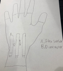
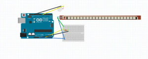
Device Requirements: Arduino Uno, 3.3v dime motor, flex resistor

Fritzing Sketch
Arduino Pseudocode

const int FLEX_PIN = A0; // Pin connected to voltage divider output

const int DIME_PIN = 7; // Pin connected to dime motor

// Measure the voltage at 5V and the actual resistance of your

// 47k resistor, and enter them below:

const float INPUT_VOLTAGE = 5;

const float RESISTANCE = 47500.0;


// Upload the code, then try to adjust these values to more

// accurately calculate bend degree.

const float STRAIGHT_RESISTANCE = 37300.0; // resistance when straight

const float BEND_RESISTANCE = 90000.0; // resistance at 90 deg


const float GOAL_ANGLE = 40.0; // ideal angle for bending

const float MAX_ANGLE = 55.0; // max angle for bending


void setup()

{

Serial.begin(9600);

pinMode(FLEX_PIN, INPUT);

}


void loop()

{

// Read the ADC, and calculate voltage and resistance from it

int flexCURRENT = analogRead(FLEX_PIN);

float flexVOLTAGE = flexCURRENT * INPUT_VOLTAGE / 1023.0;

float flexRESISTANCE = RESISTANCE * (INPUT_VOLTAGE / flexVOLTAGE 1.0);


// Use the calculated resistance to estimate the sensor’s

// bend angle:

float angle = map(flexRESISTANCE, STRAIGHT_RESISTANCE, BEND_RESISTANCE,

0, 90.0);

if(angle>MAX_ANGLE) {

digitalWrite(DIME_PIN, HIGH);

delay(500);

}

else if(angle>GOAL_ANGLE) {

digitalWrite(DIME_PIN, LOW);

}

Else {

}

delay(500);

}
Assignment 2: Expect the Unexpected

Problem

I read through a number articles and lists of problems people with disabilities face, and was intrigued by one I found that mentions that deaf people are often jumpy because they are regularly surprised by people coming up behind them. https://www.ranker.com/list/things-deaf-people-have-to-deal-with/nathan-gibson

Solution

If deaf people could be discreetly be alerted of people approaching them from behind they would be startled less often.

Proof of Concept

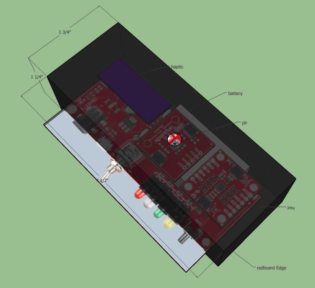
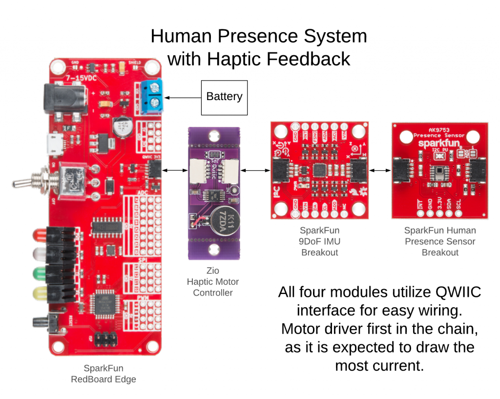
An Arduino (in this case a Sparkfun RedBoard Edge) connected to a human sensor to detect humans, a motion sensor to know when the person wearing the device is moving (to ignore humans while in motion to prevent false positives), and a vibration motor to silently alert the wearer of the device that someone is coming. By putting this all in a small case that clips to the back of someone’s belt, it should provide some warning of approaching humans.

Basic system diagram for Haptic Human Sensor
Haptic Human Sensor Physical Layout

Arduino sketch of how the logic would flow.

Aiding Visually Impaired People with Shopping

Problem: As I was thinking about ideas for this project I decided to go through my daily routine and place myself in those situations as a differently-abled person. When I thought about grocery shopping, I realized that the entire process leans on the assumption that the person can see. After doing some more digging I found this video.

In short, currently, visually impaired people usually need an assistant to guide them through the store and pick out the things they need. The problem is that visually impaired people have difficulty being independent while shopping.

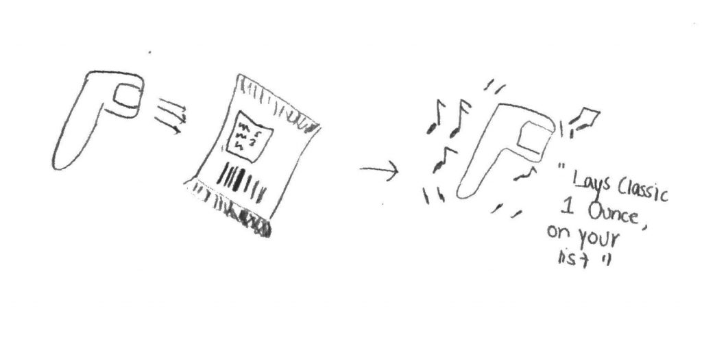
General Solution: A handheld barcode scanner which blind people can use to gather more information about the product to understand if it is what they are looking for.

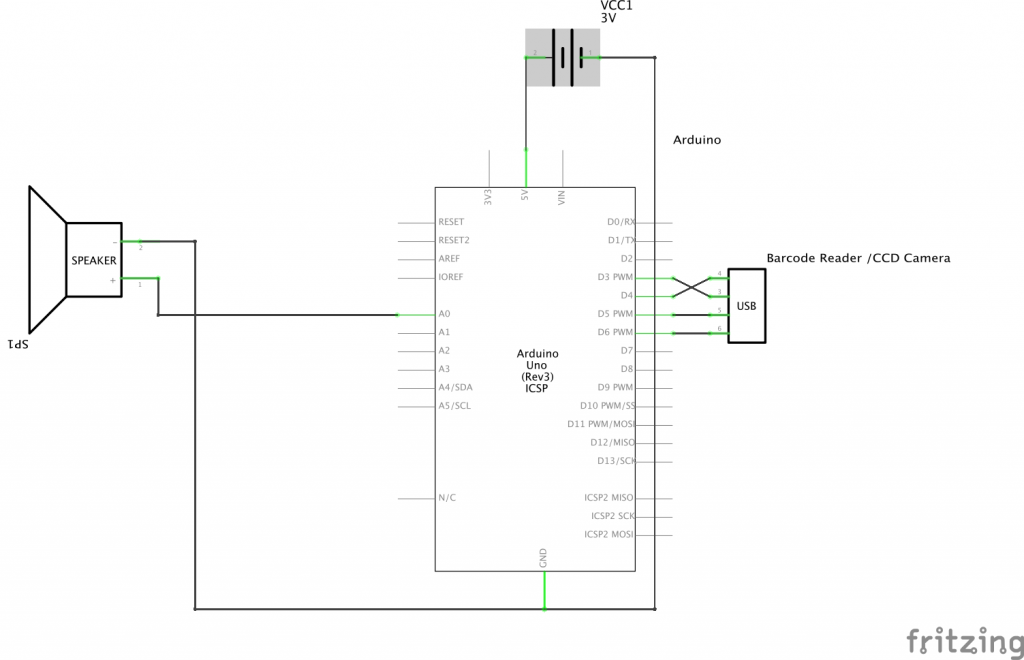
Proof of Concept: an Arduino with a barcode scanner and a speaker. If there is internet connection, the speaker can give a short description of the product. If this is not an option, user can put in names of specific products and their universal product code beforehand. When product is scanned, if it is on the list, a specific sound can be played and a different one if it is not.

Fritzing Sketch:


Drawing:


Assignment 2: Smart Entrance Lighting

Issue

Returning home after a long day is a great feeling, but for those with less-sensitive vision, it may be difficult to locate a light switch in a dimly-lit or dark environment. 

General solution

Ideally, the house should be able to sense when someone has returned, whether through the motion of the person, the opening of the door, or the location of one’s smartphone. Combining this input with a reading of the ambient light level (i.e. if it’s still bright enough outside that light coming in through windows make the house sufficiently navigable without artificial lighting), the system should determine whether it is necessary to turn on the lights. Then, once an individual has found their way past the foyer, the system could automatically turn off the lights that it had turned on earlier based on motion in other areas of the house, the turning on of other lights, or the location of a person’s smart device (using Bluetooth beacons, for example).

This solution would aid those with vision impairments and older people, whose eyes adjust slower to different lighting conditions. However, such an implementation could conceivably improve the life of a perfectly-sighted person by eliminating the need of hunting for a light switch in the dark, especially if both hands are full.

Proof of concept

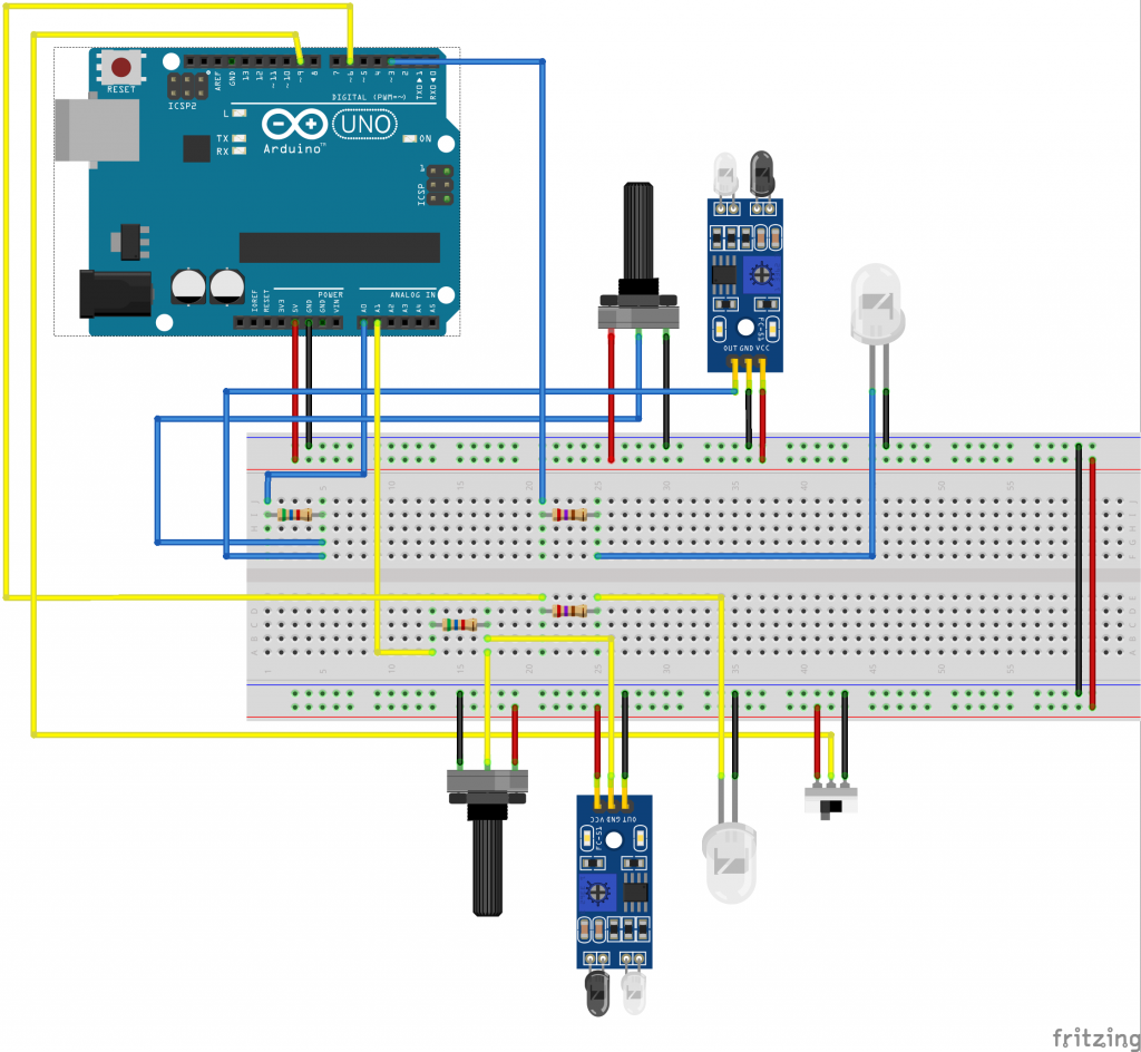
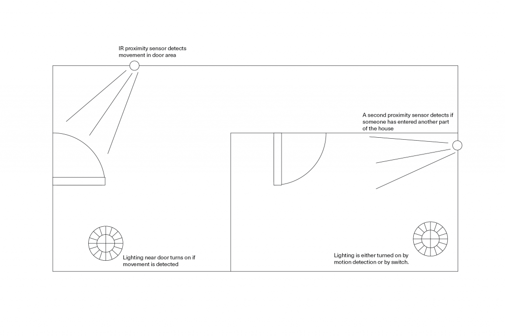
An Arduino connected to an IR proximity sensor detects when a person has entered a zone and turns on an LED. A second IR proximity sensor detects movement in another zone, and another LED is connected to a switch. If motion is detect in the second zone or if the second LED is turned on via the switch, the first LED is turned off by the controller.

Initially, I wanted to use the RCWL-0516 Doppler radar motion sensor available in the physical computing inventory, but the documentation seems thin (a GitHub project page depicts oscilloscope scans), so I decided to use a simple IR proximity sensor instead.

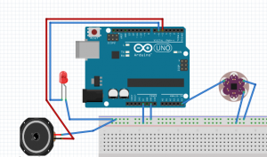
Fritzing sketch
Proof of concept schematic for a smart entrance lighting system.
Arduino sketch (untested)
const int SWITCHPIN = 9; // controls interior light
const int DOORLIGHT = 3; // LED near entrance
const int INTERIORLIGHT = 6; // LED inside house
const int DOORMOTION = A0; // IR proximity sensor near entrance
const int INTERIORMOTION = A1; // IR proximity sensor inside house
const int motionThreshold = 30; // set motion threshold here

void setup() {
  pinMode(DOORMOTION, INPUT);
  pinMode(INTERIORMOTION, INPUT);
  pinMode(SWITCHPIN, INPUT);
  pinMode(DOORLIGHT, OUTPUT);
  pinMode(INTERIORLIGHT, OUTPUT);
  
  Serial.begin(9600);
}

void loop() {
  int switchVal;
  switchVal = digitalRead(SWITCHPIN);

  int doorRead;
  doorRead = analogRead(DOORMOTION);

  int intRead;
  intRead = analogRead(INTERIORMOTION);

  if(doorRead > motionThreshold) {
    digitalWrite(DOORLIGHT, HIGH);
  }
  
  if(intRead > motionThreshold || switchVal == HIGH) {
    digitalWrite(DOORLIGHT, LOW);
    digitalWrite(INTERIORLIGHT, HIGH);
  }
}
Visual sketch
A simple floorpan showing locations for IR proximity sensors and lights.

Assignment #2 – Laundry

Problem: I live in a double duplex (quadplex?) with one washing/dryer unit in the basement.  Living on the top floor, it’s mildly inconvenient if I take the three flight journey to the basement only to find someone else already using the laundry machines.  Then I often forget I was waiting for laundry, or take too long and end up having someone else take my slot.  I believe there is a better way to not only check if its being used (more than a webcam!) but also to smartly inform behavior if it is in fact being used.  While this is somewhat a selfish assignment from my end, I do think processes like this that can allow users to not exert themselves on staircases are helpful overall.  My grandmother lived in a two-story house, walking up and down the steps daily, for probably too long, and this would ease the burden.

Solution: A system that broadcasts availability of the laundry machines, and also reminds users upon their availability after checking to ensure efficient use patterns of both.  Users are alerted via a beep and red LED.

Proof of Concept: The user would activate the system whenever they were wanting to do laundry.  If available, the system would immediately beep and let them know it was “safe” to do so.  If not, the system would remain dormant until either a) the wash cycle on the washer had passed or b) the washer stopped running.  Choice A is more of a failsafe in case the accelerometer isn’t working as it is a “maximum possible time the washer could run,” but the real meat of the concept is in B. An accelerometer responds to the washing machine movement to let the user know easily if it is in use or not.

Fritzing Sketch:

Chance Lytle Assignment 2

Basic sketch w/ speaker and LED on digital out with an overkill accelerometer only outputting its change in Y.  A less intense accelerometer would be fine, but this is the one I found first.  The only major assumption is on the accelerometer being 3 flights below the controller, but it wouldn’t be that hard to make it broadcast wirelessly.

Arduino Psuedocode:

Single-state of waiting when powered on by the user to check the laundry machine availability.

bool isTime, isInUse;
float timer = 60f * 30f; // 60secs * 30mins, adjustable dependent on wash cycle
float timeToOff = 60f * 2f;

void loop() {
    isInUse = MotionSensorStatus(); // base it off some function that reads motion input
    timer -= deltaTime; // whatever the time since powering on is
    if (!isInUse || timer <= 0f) {
        itsTime();
    }
}

void itsTime() {
    // power on LED and make a beep to notify them
    // power off system after a certain amount of time
    timeToOff -= deltaTime;
    if (timeToOff <= 0) Quit();
}


Assignment 2 — Night Light

Premise

You can’t breathe. It’s dark. Your heart is pounding through your skull. You’re sweaty. It felt so real. You know it was a nightmare. It was not real. Yet it was. You’re alone. You stare into the abyss. You try to calm down. You hope the darkness helps. But it doesn’t.

A lot of people struggle with daily nightmares, whether due to underlying anxieties, PTSD, sleeping issues or anything of the sort.

Having nightly nightmares can have large effects on your mood and health. Artwork: Kuevda©

NightmareLight

We already have Fitbits and Smart Devices that track our heart rate and track our sleep and REM cycles. Theoretically, the data is all there, so the device could tell when you’re having a nightmare. Imagine a device that emits soothing sounds and lights up with calm colors, helping soothe you after a nightmare. It feeds on the sleep data and reacts accordingly, creating a better sleeping experience.

How Would it Work?

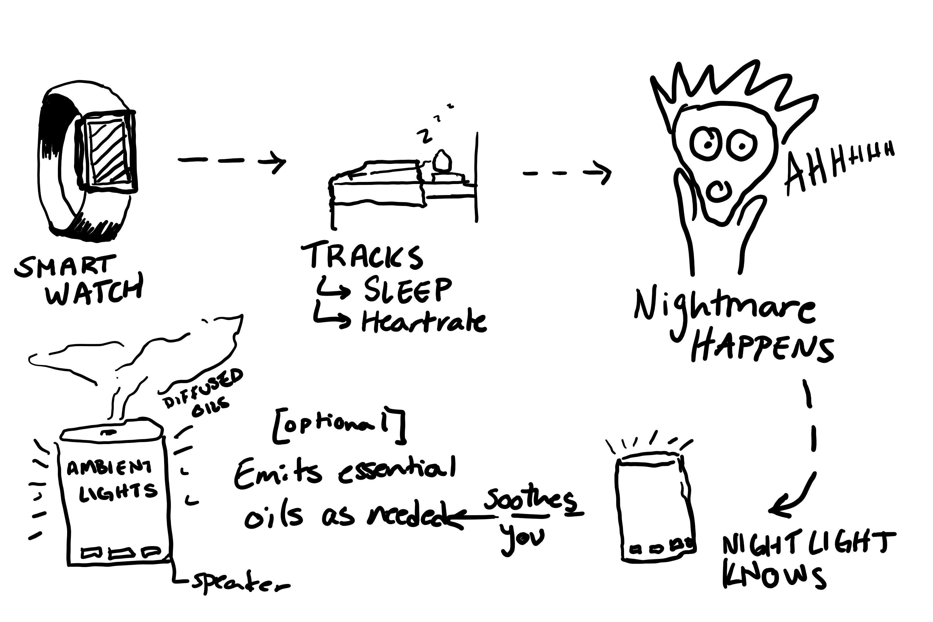
Data flow of Nightlight from watch to new Light Device

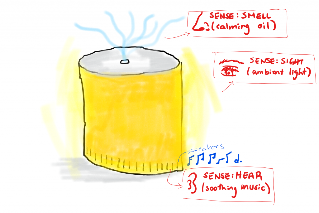
As you sleep, your smartwatch collects data as usual, and when your heart rate elevates drastically and it realizes you are having a nightmare, it signals the night light to turn on. When the night light is on, it uses the combination of smell, sound and sight to help soothe you back into sleep.


Sample product prototype sketch

In terms of Ardiuno and Fritzing sketches, I am not entirely sure on the process of reading live data using Bluetooth, but I imagine it would be uploaded on the cloud and Ardiuno would have to read the stream of data and certain functions would be called upon when they are needed.

Input is the online updating dataset (I am unsure of how this part works). Outputs are the LED, Speaker and a toggle mechanism for mist sequence.

i.e. if heart rate is above 120 bpm, then execute A, B and C.

A- release mist

B- play tune

C- turn LED to on and change color of LED from warmer to cooler red to slow down heartbeat.

Here, I used a Bluetooth micro-controller as a way to communicate between the fitbit and the nightlight.
Sample animation of how night light would adapt with your sleep.

Audiolizing Heat in a Visually Impaired Person’s Kitchen

The Problem:

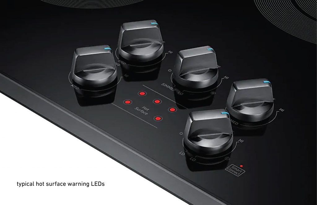
Think of the different ways that you deal with hot surfaces in your own kitchen—you might hold your hand near something to see if it’s hot, you might touch something briefly if you’re unsure of whether it is too hot to hold, or there may even be warning lights that tell you if something is safe or not to touch.

In a visually impaired person’s kitchen, however, many of these methods don’t work, and one must rely on audio queues to accomplish the same tasks. This video outlines some of the methods that the visually impaired use in order to navigate their kitchen:

Inspiration/Solution:

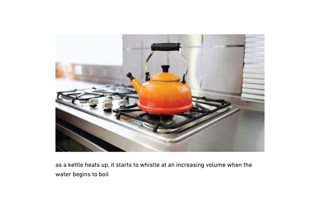
Thinking about the various audio queues present in a kitchen, one of the sounds I kept returning to was that of a kettle boiling water. I think there’s a beautiful simplicity in the way that users interact with kettles by associating the iconic steam whistle sound with heat and completeness.

My ideas is to incorporate increasing tone (similar to a kettle whistling) and apply it to stove tops in order to accomplish a couple main goals. First, if the stove top emits a tone as it heats up, visually impaired persons will be able to gauge the temperature of their surface from anywhere in the kitchen. In addition, I would like to include proximity as a variable—perhaps heat could affect the pitch of the tone while proximity to the hot surface itself affects volume. The goal is for these inclusions to not only make the kitchen safer for visually impaired persons, but more functional as well.


Proof of Concept:

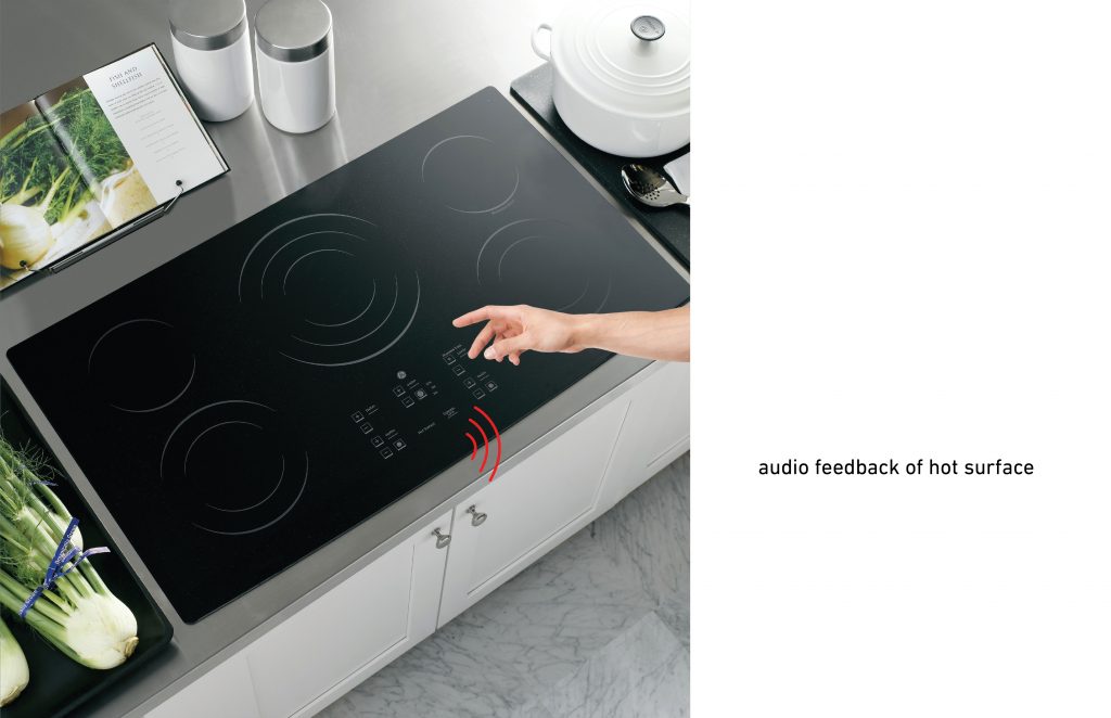
Below is a depiction of how a user might encounter tone as he/she reaches near a hot cooking surface.

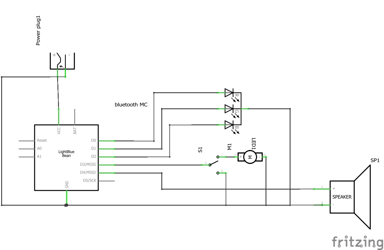
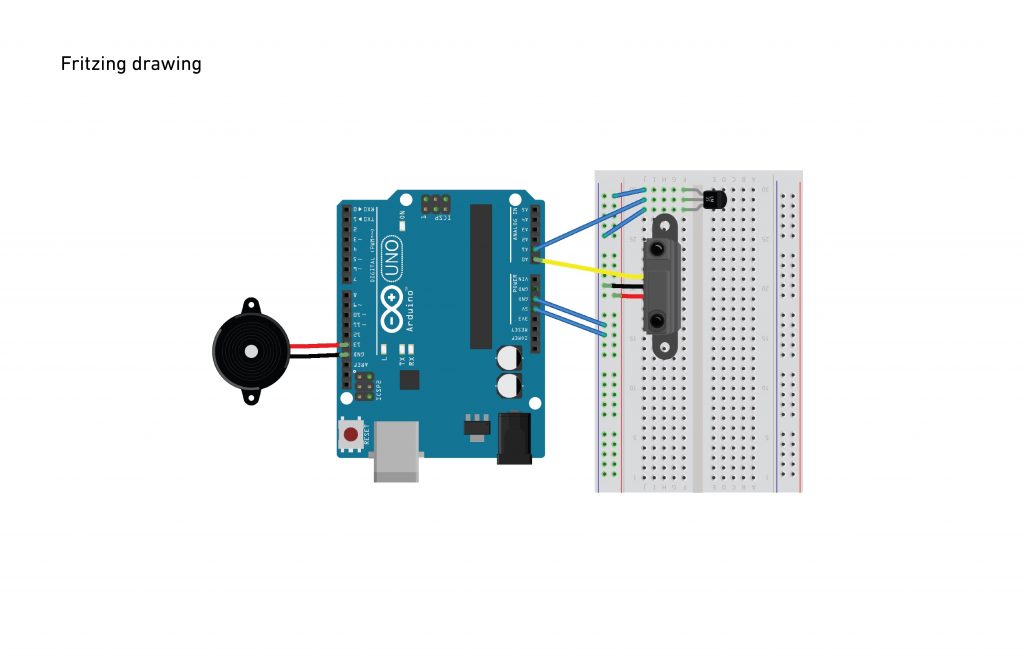
A simple circuit sketch shows the components that would be necessary to make this happen. There is a speaker to emit the tone, a heat sensor that affects the tone’s pitch, and an infrared proximity sensor to relay information to the microcontroller. Ideally these electronics would be integrated into the design of the stovetop itself, rather than as its own add-on device.

Assignment #2. Prevent alarm ringing after I got up

1) Find a problem to solve

I often woke up before my smartphone alarm rings and it keeps ringing while taking a shower, which is noisy and gives discomfort to my roommates.


2) Describe the general solution

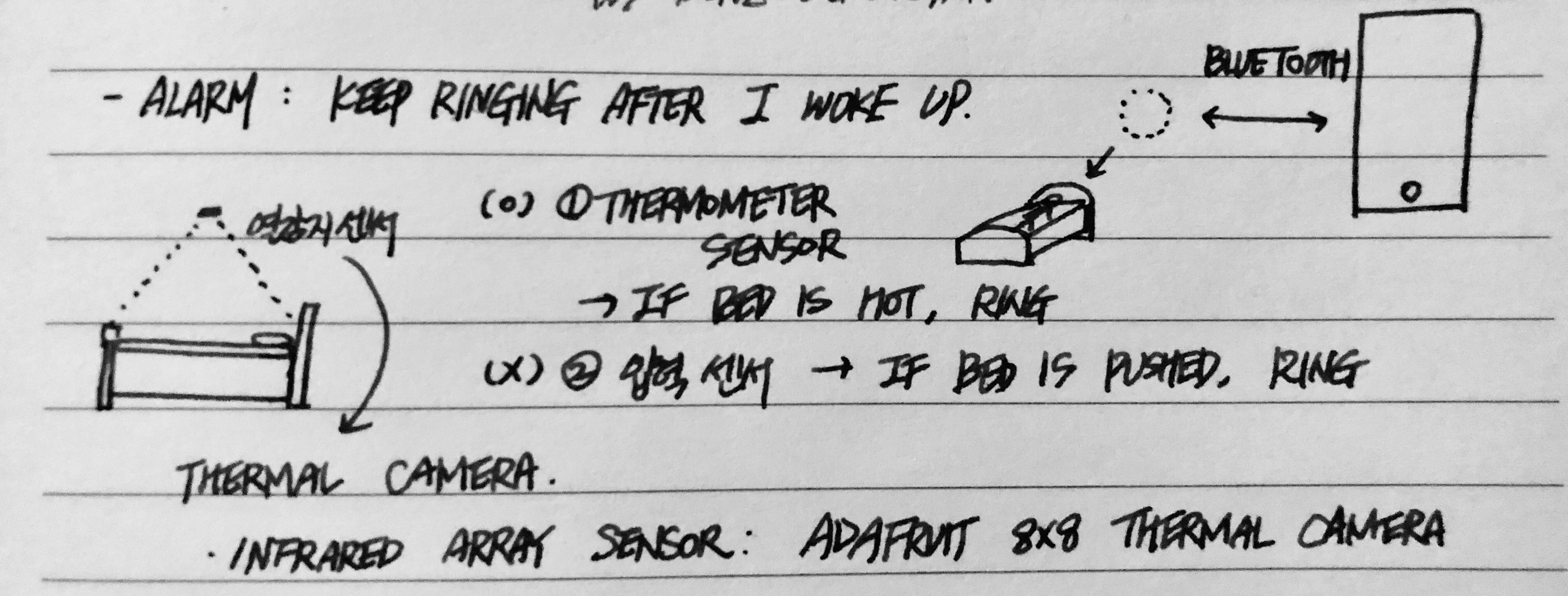
I am going to design a thermal camera device that is attached to the ceiling and scans the temperature of my bed. It is connected to my smartphone through Bluetooth. When I lie on my bed and it could detect my temperature so that allows the smartphone alarm to keep ringing. When I get up and get out of the bed, the device detects my awakeness and stop the alarm.


3) Proof of Concept

The device is composed of an infrared array sensor, a thermal camera, Bluetooth module, and a battery with an Arduino board. The camera keeps detecting the temperature changes in my bed. Since the average human temperature is around 37.5°C, I will use 36.5°C as a threshold for stopping the alarm. When the temperature of my bed goes over 36.5°C, the device allows smartphone alarm to be on, if any alarm is set. When the temperature goes under 36.5°C, which means there is no one on the bed, the device turns off the alarm not to make unnecessary noise.


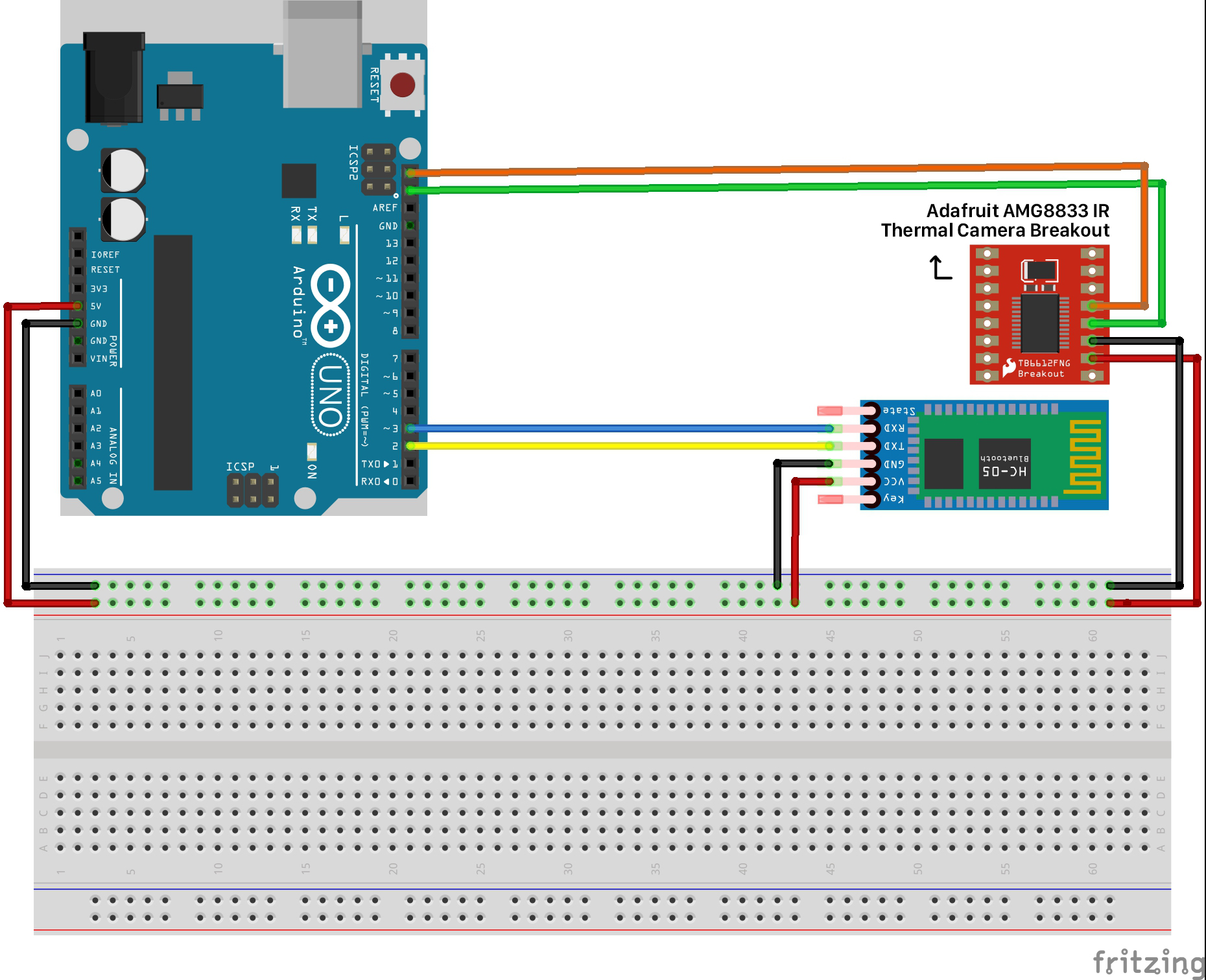
4) Fritzing Sketch

Components: Arduino Uno, Adafruit AMG8833 IR Thermal Camera Breakout, or Adafruit AMG8833 IR Thermal Camera FeatherWing, and HiLetgo HC-05 Wireless Bluetooth


5) Arduino Sketch

I tried to figure out how to code the features that I explained above for several hours, but I couldn’t. Most of all, to be honest, I have no idea how to connect the device with a smartphone through Bluetooth and control it… :

char Incoming_value = 0; //Variable for storing Incoming_value
Adafruit_AMG88xx amg;

void setup() {

Serial.begin(9600); //Sets the data rate in bits per second (baud) for serial data transmission
pinMode(13, OUTPUT); //Sets digital pin 13 as output pin

status = amg.begin();
if (!status) {
Serial.println(“Could not find a valid AMG88xx sensor, check wiring!”);
while (1);
}
}

void loop() {

if(Serial.available() > 0){
Incoming_value = Serial.read(); //Read the incoming data and store it into variable Incoming_value

Serial.print(Incoming_value); //Print Value of Incoming_value in Serial monitor
Serial.print(“\n”); //New line

if(Incoming_value == ‘1’){ //Checks whether value of Incoming_value is equal to 1
digitalWrite(13, HIGH); //If value is 1 then LED turns ON
}
else if(Incoming_value == ‘0’){ //Checks whether value of Incoming_value is equal to 0
digitalWrite(13, LOW); //If value is 0 then LED turns OFF
}
}

float pixels[AMG88xx_PIXEL_ARRAY_SIZE];
amg.readPixels(pixels);

if(pixels >= 36.5) {
//turn the alarm of the smartphone off
}
else{
//keep the settings of the alarm of the smartphone
}

}


6) Proof of Concept Sketches


Hey Mi

Problem:

Not being able to hear when someone is calling your name/trying to get your attention, whether in the context of a workplace, airport, etc.

A General Solution:

A device that would physically or visually notify an individual when sensing that someone is trying to get their attention.

Proof of Concept:

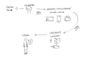
An Arduino with a microphone/other device with a microphone and LEDs/Servo.  Specific words cause the LEDs to flicker/Servo to make movements to grab the individual’s attention. and plays a sample on the speaker stating the status of a configuration.  Example: when sensing that the user’s name is being called, the device will flicker/move.

Fritzing Sketch:

The Fritzing sketch shows diagrammatically how the microphone would input information to the Arduino as well as how the LED/Servo would be connected to the output pins. Not pictured, is that the Arduino would have to be connected to some battery source.

Arduino Sketch:

I’m not familiar with voice recognition with Arduino, but I found a project that has done it before with specific hardware (link here) and there are other devices that surround us that would be able to accomplish the same audio processing as well (ex. smartphones, smart watches). The results of the audio processing would trigger a digital output to the LEDs/Servo to communicate to the user.

Proof of Concept Sketches:

The flow of data starts with outside audio reaching the microphone which then is fed into the Arduino (or other audio processing capable device) which will decide whether or not to send a signal to the LED/Servo/solenoid based on whether the sound recognizes the users name. If the name is recognized, the signal is sent and it grabs the user’s attention.


Assignment 2: Raising a Digital Hand

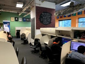
Find a problem to solve:   All of the 80 first-year ETC students take a class called Building Virtual Worlds that splits them into one of three different roles: sound designer, programmer, or artist. Students essentially make new video games every two weeks, usually on different software or hardware platforms they are learning about as they build. As you can expect, this means there are a lot of questions for TAs to answer; however, not all questions can be answered by each TA. We have at least 6 different types of TA that all specialize in their own field/software/etc. One of the biggest problems in the class is that when students ask for help, the TA on duty never seems to specialize in the field they have a question, so it takes them finding another TA to answer it. This game of telephone usually results in a) longer wait times for each student, b) fewer total questions being answered, or c) questions being answered by TAs that may not be qualified (3D modelers answering hardware coding questions for example). In addition to all of this, all 80+ students sit in the same office space so it is really a test of a student’s luck whether or not a TA will see them when he or she walks by or if they have to wait for them to circle back around.

Describe the general solution: Students should be able to request help from specific TAs to answer their specific questions quickly and easily. TAs should also have a system so they can track what types of questions are asked where, the order in which they are asked, and who is going to answer them. Both parties should also both be able to see the status of the question (asked, waiting, answering, answered, etc.). 

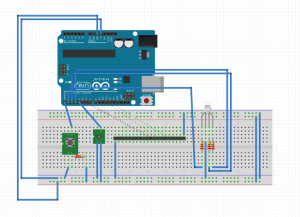
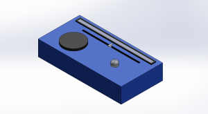
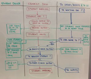
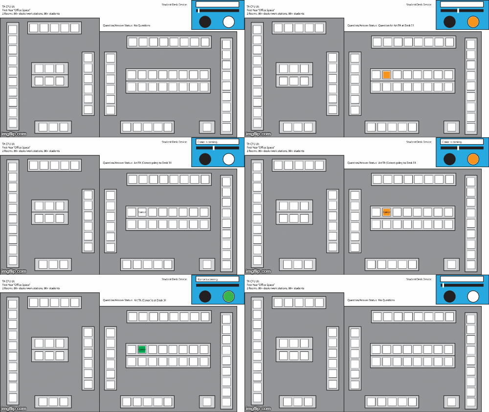
Proof of Concept:  An Arduino with a button, slider/potentiometer input, RGB LED, an LCD monitor and a computer program interface with a state machine of the question-asking/answering process.  When students have a question, they can adjust the slider to select which type of TA they would like help from. The LED would turn on (in the corresponding color of the TA group) to signal that the TAs have been alerted. On the TA-facing computer program, TAs can see a map of where the students are and their questions based on the colors. TAs can start the answering process by selecting and attaching their name to a question, which is communicated to the student’s device through 1) the LED flashing and 2) the name of the TA appearing on the screen because they are on their way down to help. Once at the student’s desk, the TA can press and hold the button on the student’s device to alert the other TAs that the student is being helped by changing the color of the LED on the device and on the UI. Finally, once the question is answered, the TA can press and hold the device’s button again to turn the LED off.

Fritzing Sketch: Disclaimer – likely not accurate, playing with software and different components.

First Iteration of Device Model:           

Student & TA User Journey:                     

Demo TA-facing UI & Student Device: