Woarb update: the waorb is becoming warmer.
Seriously though… Here’s the waorb prototype circuit.
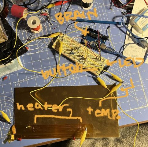
As you can see it’s basically the circuit from the waorb proposal (missing the on/off switch, heater being powered by an external power supply) with the addition of a momentary switch and a cockroft-walton ladder to power the MOSFET switching the heater.
Let’s break it down a bit more!
HEATER ELEMENT TEST
The heater is made from 40 gauge steel wire (ie. about human hair width)–and in order to achieve the right resistance (~10 ohms). The batteries I intend to use in the final waorb should be able to create about a 6.6w heater so I tested the heating elements to determine how well they could heat the brass using A and V which would produce 6.6w.
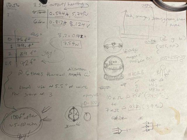
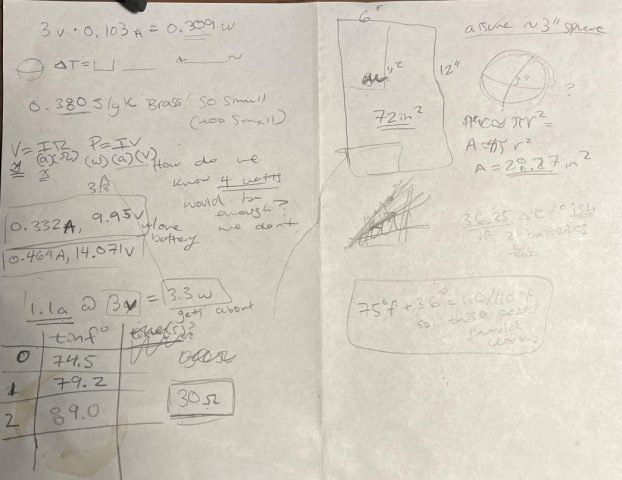
Above: my horrible math notes.
I found that on the brass sheet (about 6 times as much brass as in the waorb) I was able to heat the brass to about 89.0 degrees f.
This was important because I now know:
- That the woarb should perform as hoped (heating power and thermal tape attachment wise). The heating elements I created don’t catch fire.
- The number of wires at what length I will need in the final waorb (resistance is directly proportional to length of wire and inversely proportional to number of wires of said length). I will need 3 wires at ~5.5″ for each heating element.
CIRCUIT BUILDING
I then built the circuit needed to power on an RGB LED on a breadboard with an Arduino and installed Arduino. (As shown in the design).
After that I built the temp circuit (as shown in the design) and used the serial port on the Arduino to test it was working. Once it was working I took readings to calibrate it.
Reading | temp in F | temp in C | Temp in 10ths of C
880 71.5 22.2 222
680 85.5 30.1 301
580 96.9 35.5 355
640 94.2 35 350
I used these values to find a line of best fit to convert the sensor reading into 10ths of degrees C (so they can be stored accurately without floating point numbers).
After this I added the heater element back into the circuit (almost as shown on the design, added a cockroft-walton ladder to make the MOSFET work correctly).
After this I added a momentary switch to change modes in the final program.
PROGRAM
Currently the program is able to: switch between modes when the mom switch is clicked–showing a different LED color for each, take the temperature when the switch is single clicked in listening mode–showing a white flash from the LED, record the temperature into in 10ths of degrees c to an array.
TODO: add the heater control, make the LEDs change dynamically with temperature in listen and repeat mode. I’m sure some other stuff I’m forgetting.
//vars for button stuff bool pressed;
int pressnum = 0;
unsigned long pressMil; //there is a bug where milli() runs out of space and makes measurements invalid… maybe fixed abs
int mode = 0; int test; //vars for recalibrating the temp sensor (form: y=mx+b)y is degrees in 10ths of c, x is sensor data number
float m = -0.4639; int b = 629; //array for temps recorded
int currentSlot = 0; //check to make sure this is correct
int tempsRec[100];
//write mode 0 here (ie. startup/idle mode)
void idle () {
analogWrite(9, 0);
analogWrite(10, 0);
analogWrite(11, 150); }
//write mode 1 here (ie. listening mode)
void listens () {
//temp sensing
int tempSensor = analogRead(A5);
int temp = m*tempSensor+b; //temp in 10ths of degrees C
//LEDS
analogWrite(9, 0);
analogWrite(10, 150);
analogWrite(11, 0); }
//write the picture function here (ie. take temp and store it)
void picture () {
analogWrite(9, 255);
analogWrite(10, 255);
analogWrite(11, 255);
int tempSensor = analogRead(A5);
int temp = m*tempSensor+b; //temp in 10ths of degrees C tempsRec[currentSlot] = temp; currentSlot++;
delay(500);
analogWrite(9, 0);
analogWrite(10, 0);
analogWrite(11, 0); }
//write mode 2 here, (ie. run the heater correctly)
void repeat () {
analogWrite(9, 150);
analogWrite(10, 10);
analogWrite(11, 0); }
//IRS
void switchPressed () {
pressed = true;
pressMil = millis(); }
void setup() {
// put your setup code here, to run once:
pinMode(9, OUTPUT);
pinMode(10, OUTPUT);
pinMode(11, OUTPUT);
digitalWrite(3, HIGH);
attachInterrupt (digitalPinToInterrupt (3), switchPressed, CHANGE); pinMode(A5, INPUT);
analogReference(INTERNAL);
Serial.begin(9600); }
void loop() {
// put your main code here, to run repeatedly:
//this whole part controls the mode selection and picture action
test = pressMil+500-abs(millis());
if (pressed == true) {
pressnum++;
delay(250);
pressed=false; }
if (test < 0) { pressnum=0; }
else if (pressnum >= 2) { mode++; delay(500); }
if (test > 0 && mode == 1 && pressnum == 1) { picture(); }
if (mode==3) { mode = 0; }
//these run the mode code depending on the mode
if (mode==0) { idle(); }
else if (mode==1) { listens(); }
else if (mode==2) { repeat(); }
}