Looking Outwards – 04

Zimoun – Sound Sculptures

Zimoun’s sound sculptures revolve around using industrial and everyday materials such as cardboard and manipulates them in a mechanical way that when in motion, creates immersive and beautical sounds. His sculptures are typically installation pieces that spin, turn, oscillate ect, to create a depth in the sounds. I admire his works especially because of the materials he uses; Zimoun manages to discover the hidden sounds of everyday objects and exhibits them in a way that produces almost a spatial experience, derived from a series of the same object. 

I believe that the motion of the objects are generated by programming the oscillations of the corresponding string or wire, which leads to the oscillation of the object. 

The artist, Zimoun has always been interested in both sound art and visual art, which has helped him in his projects; his sound sculptures are both visually and phonetically aesthetic and theses components work together to create the immersive experience. 

Rowing boats

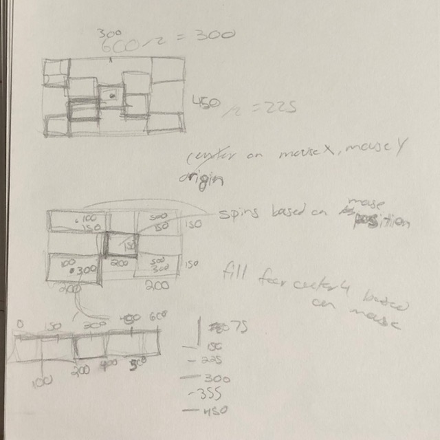
My string art uses loops to generate wave patterns to create an ocean. In the process, I am trying to control the lines carefully by adjusting the start and end points’ values.

//Jason Jiang
//Section E

//Setting variables 
var dx1;
var dy1;
var dx2;
var dy2;
var numLines = 10;

//Creating Sky
function setup() {
    createCanvas(300, 400);
    background(135, 206, 235, 50);
    }


function draw() {
    
    //Waves
    stroke(0, 100, 184);
    var x1 = -30;
    var y1 = 300;
    var x2 = 600;
    var y2 = 500;
    strokeWeight(0);
    line(-30, 300, -50, 400);
    line(600, 300, 400, 500);
    strokeWeight(1);
    dx1 = (-50-(-30))/numLines;
    dy1 = (400-300)/numLines;
    dx2 = (600-300)/numLines;
    dy2 = -(500-300)/numLines;
    for (var i = 0; i <= numLines; i += 1) {
        strokeWeight(i*0.1)
        line(x1, y1, x2, y2);
        x1 += dx1;
        y1 += dy1;
        x2 += dx2;
        y2 += dy2;
    }
    

    x1 = 0;
    y1 = 300;
    x2 = 500;
    y2 = 500;
    strokeWeight(0);
    line(0, 300, -50, 400);
    line(400, 150, 500, 500);
    strokeWeight(1);
    dx1 = (-50-0)/+numLines;
    dy1 = (400-300)/numLines;
    dx2 = (500-400)/numLines;
    dy2 = -(500-150)/numLines;
    for (var i = 0; i <= numLines; i += 1) {
        strokeWeight(i*0.1)
        line(x1, y1, x2, y2);
        x1 += dx1;
        y1 += dy1;
        x2 += dx2;
        y2 += dy2;
    }


    x1 = -100;
    y1 = 300;
    x2 = 400;
    y2 = 300;
    strokeWeight(0);
    line(-100, 300, -250, 500);
    line(300, 200, 400, 300);
    strokeWeight(1)
    dx1 = (-150+50)/+numLines;
    dy1 = (500-300)/numLines;
    dx2 = -(500-400)/numLines;
    dy2 = -(300-200)/numLines;
    for (var i = 0; i <= numLines; i += 1) {
        strokeWeight((numLines-i)*0.1)
        line(x1, y1, x2, y2);
        x1 += dx1;
        y1 += dy1;
        x2 += dx2;
        y2 += dy2;
    
    }


    x1 = -100;
    y1 = 300;
    x2 = 400;
    y2 = 320;
    strokeWeight(0);
    line(-100, 320, -350, 450);
    line(200, 350, 150, 320);
    strokeWeight(1)
    dx1 = (-250-150)/+numLines;
    dy1 = (450-250)/numLines;
    dx2 = -(350-300)/numLines;
    dy2 = -(400-350)/numLines;
    for (var i = 0; i <= numLines; i += 1) {
        strokeWeight((numLines-i)*0.1)
        line(x1, y1, x2, y2);
        x1 += dx1;
        y1 += dy1;
        x2 += dx2;
        y2 += dy2;
    
    }
    

    x1 = -150;
    y1 = 200;
    x2 = 350;
    y2 = 350;
    strokeWeight(0);
    line(-150, 200, -250, 400);
    line(300, 300, 350, 350);
    strokeWeight(1)
    dx1 = (-250+100)/+numLines;
    dy1 = (300-100)/numLines;
    dx2 = -(500-400)/numLines;
    dy2 = -(300-200)/numLines;
    for (var i = 0; i <= numLines; i += 1) {
        strokeWeight((numLines-i)*0.05)
        line(x1, y1, x2, y2);
        x1 += dx1;
        y1 += dy1;
        x2 += dx2;
        y2 += dy2;
    
    }
    

    //Boat
    //Lower Part
    x1 = 85;
    y1 = 260;
    x2 = 130;
    y2 = 270;
    strokeWeight(0);
    line(85, 260, 90, 272);
    line(130, 270, 120, 280);
    strokeWeight(1)
    dx1 = 2*(90-85)/numLines;
    dy1 = 2*(272-260)/numLines;
    dx2 = 2*(120-130)/numLines;
    dy2 = 2*(280-270)/numLines;
    for (var i = 0; i <= 0.5*numLines; i += 1) {
        strokeWeight((numLines-i)*0.15)
        stroke(i);
        line(x1, y1, x2, y2);
        x1 += dx1;
        y1 += dy1;
        x2 += dx2;
        y2 += dy2;
    
    }
    //Upper Part
    x1 = 92;
    y1 = 259;
    x2 = 120;
    y2 = 265;
    strokeWeight(0);
    line(92, 261, 110, 230);
    line(120, 267, 110, 230);
    strokeWeight(1)
    dx1 = (110-92)/numLines;
    dy1 = (230-261)/numLines;
    dx2 = (110-120)/numLines;
    dy2 = (230-267)/numLines;
    for (var i = 0; i <= numLines; i += 1) {
        strokeWeight((numLines-i)*0.15)
        stroke(i+100);
        line(x1, y1, x2, y2);
        x1 += dx1;
        y1 += dy1;
        x2 += dx2;
        y2 += dy2;
    
    }

    //Sun
    x1 = 200;
    y1 = 59;
     //Outer Ring
     for (var i = 0; i <= 10*numLines; i += 1) {
        stroke(253, 184, 19, 50)
        strokeWeight(1)
        push()
        translate(x1, y1);
        rotate(radians(i*180/numLines));
        line(0, 0, 0, 100);
        pop()
 
    }
    //Inner Ring
    for (var i = 0; i <= 10*numLines; i += 1) {
        stroke(200, 92, 60)
        strokeWeight(1)
        push()
        translate(x1, y1);
        rotate(radians(i*0.5*180/numLines));
        line(0, 0, 0, 50);
        pop()
    }

noLoop();

}

Light and sound

This project is all about sound visualization. Amay Kataria visualizes sound by constructing 24 light beams arranged like a synthesizer. Each time there is a sonic input, the corresponding light turns on by performing different notes, the light flickers and continuously changes its pattern. The light and sound are tied in a way that, fundamentally, they are all waves that mark their presence in the outer world. Besides, it also connects to the inner world, which is people’s minds, since user inputs control all patterns.

Performers controlling the installation

The artists showcase his artistic sensibility by developing a system that mimics the human brain, which receives inputs from multiple sources and stores it in the database, which is interpreted and expressed through light and sound. Personally, I like how the system takes into account all users’ input at the same time which emphasizes each individual as a part of the community. It connects individuals in an anonymous way that highlights the hive-mind of humanity.

LO week3

http://www.johnedmark.com/

I am so fascinated by John Edmark’s Golden Angle – Bloom (http://www.johnedmark.com/phifib/2016/4/28/blooms-strobe-animated-phi-based-sculptures). The work is by 3d printing, the shape itself is amazing enough, it’s the golden and sweet spot where math and art intersect. The ratio is called phi (ϕ), the same ratio that nature employs to generate the spiral patterns we see in pinecones and sunflowers. 
That reminds me of when I made spirals, the number is so difficult to find, and the most beautiful curve is defined by only a few numbers that I had to test out. Then I got into this rabbit hole: Fermat’s spiral (https://flyingpudding.com/projects/florets/applet/) trying to figure out how the mathematical format is associated with the image. And I feel emotional about how the universe is created in a perfect way and we humans get to study it.

Not only the shape itself of the 3D printing object itself but the way he presents it – a video in which the object spins. I didn’t realize the magic until I looked deep – the object looks smoothly blooming. According to the artist “Rather than using a strobe, the camera was set to a very short shutter speed in order to freeze individual frames of the spinning sculpture. ”By then, the artist adds another dimension to the work – time. And with camera technology, made this magic happen.

project3

sketch
   //Qixin Zhang
   // section E

    var x = 1
    var y = 1
    var angle = 0

function setup() {
    createCanvas(600,600);
        background(0);
  

}


function draw() {
    blendMode(SCREEN);
    translate(width/2,height/2);
  rotate(radians(angle+1))
    //fill(254,32,32);
   // noStroke ();
     // circle (0,0,1);

  
  if (mouseX <width/2 )  {
    
     x = x+0.3;
    y = y+0.3;
    angle = angle +22;
    fill(255,0,0);
    noStroke();
    scale(x/50)
    rotate(radians(angle));
    translate(x,y);
    circle (0,0,20);
    
    
  } else if (mouseX >width/2 ) {
    x = x+0.3;
    y = y+0.3;
    angle = angle -21;
    fill(156,0,0);
    noStroke();
   
    rotate(radians(angle));
    translate(x,y);
    circle (0,0,20);
  }


}

I am fascinated by the spiral, so i used mouseX and mouseY to control the direction of spinning angle

LO 03: Reverberating Across the Divide by Madeline Gannon

This project revolves around usage of real time context scanning as data input and converting it to physical objects through chronomorphologic modeling. The most interesting part is the integration of real time scanning, computational generative modelling, and rapid prototyping tools to realize the design.  The complexity of the object can be controlled using parameters in the computational modelling software which in turn provides control over the local as well as global model.

The final form reverberates the sensitivity between the context, computer generated model as well as the fabricated physical object, true to the title.  

Reverberating Across the Divide: Digital Design Meets Physical Context from Madeline Gannon on Vimeo.

Project 3 – Dynamic Drawing

Controls:
– upper right corner = scale up
– lower left corner = scale down
– up & down = triangles move to the right
– click & hold on triangle = rotate
– hover over triangle = fade to white

Originally I wanted to make a field of triangles, where the triangle & neighboring triangles would flip out into a ripple. Initial generation of the triangular grid was easy, but when I wanted to proceed with more complicated maneuvers, I found my self going back to and rewriting my code so it was more structured and centralizing all the important parameters I wanted my operations to depend on.


In particular, I really struggled with the rotation implementation. P5’s scale operation acts as a blanket technique, operating on all the geometries called after it, whereas I wanted triangles to rotate individually, meaning I had to parse through every single triangle individually to find the one I wanted to rotate. When rotating, wiggling the mouse causes the rotation to flicker, as the file is looping through draw to update the new mouse position, so keeping the mouse still when rotating pieces is advised. The rest were relatively straightforward to implement.

sketch
// Tsz Wing Clover Chau
// Section E


function setup() {
    createCanvas(600, 600);
    background(220);
    text("p5.js vers 0.9.0 test.", 10, 15);
    frameRate(200);
}

var init = true;

var row = 0;
var col = 0;
var selCol = 0;
var selRow = 0;

var offset = 30;

var n = 3;
var l = 0;


var leftX = 0;
var rightX = 0;
var ptX = 0;
var leftY = 0;
var rightY = 0;
var ptY = 0;

var mX = 0;
var mY = 0;

var wait = 70;

var sizeCounter = 1;


let neighC = [255, 255, 255];

let triList = [];


function area(x1, y1, x2, y2, x3, y3) {
    return abs(((x1*(y2-y3)) + (x2*(y3-y1))+ (x3*(y1-y2)))/2);
}

function inbounds(x1, y1, x2, y2, x3, y3, mouseX, mouseY){
    let A = area(x1, y1, x2, y2, x3, y3);
    let A1 = area(mouseX, mouseY, x2, y2, x3, y3);
    let A2 = area(x1, y1, mouseX, mouseY, x3, y3);
    let A3 = area(x1, y1, x2, y2, mouseX, mouseY);
    return (A == A1+A2+A3);
}


function draw() {
    noStroke();
    background(220);
    
    l = (width-(offset*(n-1)))/n;
    var h = sqrt(3)/2 * l; 

    // init triangle grid
    if (init){
        if (row %4 == 0){
            leftX = (col*(l+offset)) + offset;
            rightX = leftX + l;
            ptX = leftX + l/2;

            leftY = (row/2*(h+offset/2)) + offset;
            rightY = leftY;
            ptY =  leftY + h;

            midY = leftY + h/2;


        } else if (row %4 == 2) {
            leftX = ((col-0.5)*(l+offset)) + offset;
            rightX = leftX + l;
            ptX = leftX + l/2;


            leftY = ((row/2)*(h+offset/2)) + offset;
            rightY = leftY;
            ptY =  leftY + h;

            midY = leftY + h/2;

        } else if (row %4 == 3) {
            leftX = ((col - 0.5)*(l+offset)) + l/2 + offset*(3/2);
            rightX = leftX + l;
            ptX = leftX + l/2;

            leftY = (int(row/2)*(h+offset/2)) + h + offset;
            rightY = leftY;
            ptY = leftY - h; 

            midY = leftY - h/2;


        } else {
            leftX = ((col-1)*(l+offset)) + l/2 + offset*(3/2);
            rightX = leftX + l;
            ptX = leftX + l/2;

            leftY = (int(row/2)*(h+offset/2)) + h + offset;
            rightY = leftY;
            ptY = leftY - h;  

            midY = leftY - h/2;
        }
        midX = ptX;

        var cShift = false;
        var a = 90;
        let selC = [0, 0, 0];

        append(triList, [leftX, leftY, rightX, rightY, ptX, ptY, selC, cShift,
                         a, midX, midY, row, col]);

    } else {

        //controlling SCALE
        if (wait == 0 & mouseX < width/8 && mouseY < height/8){
            sizeCounter += 0.01;
        } else if (sizeCounter > 1 & mouseX > width/4 && mouseY > height*3/4){
            sizeCounter -= 0.01;
            }
        scale(sizeCounter);


        for (let i = 0; i< triList.length; i++) {
            mX = mouseX;
            mY = mouseY;
            elem = triList[i];


            fill(elem[6]);

            //controlling POSITION
            if ((mouseY > elem[2] & mouseY > elem[5]) ||
                (mouseY > elem[2] && mouseY < elem[5])){
                    elem[0] -= 0.5;
                    elem[2] -= 0.5;
                    elem[4] -= 0.5;
                    elem[9] -= 0.5;
                }

            if (inbounds(elem[0], elem[1], elem[2], elem[3], 
                         elem[4], elem[5], mX, mY)) {
                elem[7] = true;

                //controlling SHADE
                if (elem[7]){
                    for (let i = 0; i< 3; i++){
                        elem[6][i] += 10;
                    }
                }
                // controlling ROTATION  (don't move mouse during rotation - it flickers)
                if (mouseIsPressed){
                    push();
                    fill(255, 255, 255);
                    translate( elem[9], elem[10]);
                    rotate(radians(elem[8]), [elem[9], elem[10], 0]);
                    translate(-elem[9], -elem[10]);
                    triangle(elem[0], elem[1], elem[2], elem[3], elem[4], elem[5]);
                    pop();

                    elem[8] += 3;
                }
            } else {
                elem[7] = false;
            }
            if (elem[8] == 90){
                triangle(elem[0], elem[1], elem[2], elem[3], elem[4], elem[5]);
            }
        }
    }


    if (col > n){
        row ++;
        col = 0;
        if (rightY +h > height) {
        init = false;
        }
    } else {
        col ++;
    }

    if (wait > 0){
        wait --;
    }
}

Looking Outwards 03: Computational Fabrication

Aguahoja (1 – 3)
Contributors: Neri Oxman & MIT Mediated Matter Group
2018 – 2021

Physical installation at MIT Media Lab in February 2018

The project I have chosen is the Aguahoja collection (Aguahoja 1 & Aguahoja 2) by the Mediated Matter Group at MIT which are a series of pavilions and associated artifacts made from digitally fabricated biodegradable composites (ie. a cellulose-chitosan-pectin-calcium carbonate compound.
After use, these ‘structural skins’ can be programmed to degrade in water in a process called “environmental programming”.

Prototypes at MIT Media Lab in February 2018

What I admire is how ‘self-sufficient’ the project is and how integrally the ‘cradle-to-cradle’ aspect of its design concept were incorporated. The lack of need for a secondary load bearing structure conventionally needed for stability and form is forgone in favour of a material with these features embedded into the molecular structure, giving an unique elegance. I also appreciate the rigor that the researches put into development of their ‘library’ of functional biopolymers, allowing them to develop an extensive range of biocomposites that can respond to different stimuli (temp / heat, humidity, light, etc.).

According to the paper “Flow-based Fabrication: An integrated computational workflow for design and digital additive manufacturing of multifunctional heterogeneously structured objects”, published by the Mediated Matter Group in 2020, their work flow “encodes for, and integrates domain-specific meta-data relating to local, regional and global feature resolution of heterogeneous material organisations.” I interpreted it to mean that they had a mesh-free geometric primitive onto which they associated the material properties and variable flow rates of various water-based materials, and then tested/ demonstrated the physical properties of these simulations with a robot arm and multi-syringe multi nozzle deposition system. This in context of another published paper “Designing a Tree: Fabrication Informed Digital Design and Fabrication of Hierarchical Structures” implies that the biomolecules of these biomaterials are deliberately chosen to “maximize desired basic-to-acidic and hydrophobic-to-hydrophilic transitions”, while “decay maps” show the degradation of the material over time in relation to various environmental factors. Clearly, a lot of categorization and material mapping occurs on the nano scale, followed most likely by an optimization algorithm (potentially a Machine Learning program) that determines an optimal molecular organisation to be fed into robot arm & multi nozzle deposition system depending on the environmental parameters encoded for.

Robot arm depositing composite material fibers

Arguably, this is a manifestation of the “Form Follows Function” creed where an artifact/ structure’s physical form emerges as result of the functions it has to serve. This is supported by the quote “The Aguahoja 1 platform is… where shape and material composition are directly informed by physical properties (eg. stiffness and opacity), environmental conditions (eg. load, temperature, and relative humidity) and fabrication constraints (eg. degrees-of-freedom, arm, speed, and nozzle pressure), among others.” Thus, it is inferred that any artistic sensibilities exhibited by the work were encoded via the prioritization and curation of specific environmental & physical factors.

Links:
https://www.media.mit.edu/projects/aguahoja/overview/
https://www.media.mit.edu/projects/aguahoja-iii/overview/
https://web.archive.org/web/20211015194534/https://mediatedmattergroup.com/publications-2-1/2018/10/16/designing-a-tree-fabrication-informed-digital-design-and-fabrication-of-hierarchical-structures
https://web.archive.org/web/20211015184725/https://mediatedmattergroup.com/publications-1/2018/10/7/flow-based-fabrication-an-integrated-computational-workflow-for-design-and-digital-additive-manufacturing-of-multifunctional-heterogeneously-structured-objects

Project 3: Dynamic Drawing

sketch
// Ana Furtado 
// Section E
// Project 3 -- Dynamic Drawing

var angle = 0;

function setup() {
    createCanvas(600, 450);
}

function draw() {
    background(max(mouseX, mouseY)); // gets lighter and darker 
    fill(255); //white center rectangle
    strokeWeight(mouseX); // gets bigger as moves to the right
    rotate(radians(angle)); 
    rectMode(CENTER);
    rect(300, 225, 200, 150); //center white rectangle
    angle += (min(mouseX, mouseY)); ///spins rectangles according to mouse
    fill(255);
    //outer rectangles grow bigger and smaller and overlap
    rect(100, 75, 200, mouseY); // outer rect L1
    rect(100, 375, 200, -mouseY); //outer rect L2
    rect(500, 75, 200, mouseY); //outer rect R1
    rect(500, 375, 200, -mouseY); //outer rect R2

}

I by thinking about what could change by moving mouseX and mouseY. The most difficult part was getting the rotating around the origin to work.

LookingOutwards – 03

I like the wood bending project done by Sima Bdeir during Jeremy Ficca’s ASO studio as a part of the MAAD program at CMU. I admire how natural the structure appears. I admire how the light, material, and how it rests on ground were all taken into consideration. I believe some kind of generative software along with Rhino was used to generate the form and the structure was built using wood bending techniques, laser cutter, and metal supports. I think the creator’s artistic sensibilities come out in the unique form. I believe they took inspiration from nature and rethought how that could be practically used in this structure. Although, I do not understand the purpose of the curves near the back. They do not appear to seats, perhaps they could be to store things, or simply for design purposes. Overall, I believe the generative process used to create this structure makes it interesting to walk through.

Master of Advanced Architectural Design — CMU School of Architecture