Julie Choi – Looking Outwards – 03

These are some samples that the MIT media lab produces using their voxel-based 3D printing.

The MIT media lab consist of many research assistants who are both engineers and artists. They recently released a new project that produces data into a physical form through a voxel-based multi-material 3D printing. This project was very interesting because it converts data sets to process the information through a modernized 3D printer that allows the user to produce the intricate details of the art. Most 3D printing analysis the basic form and physicality of an object so that people can take a step forward to analyze the shape and size, but this voxel printing produces elaborated forms with different texts and materials of choice and alleviates altering data that possibly might lead to data loss.

This is one of the brain models that MIT media lab produced with their voxel-based 3D printer. “White matter tractography data physicalization of the human brain, visualizing bundles of axons, which connect different regions of the brain.”

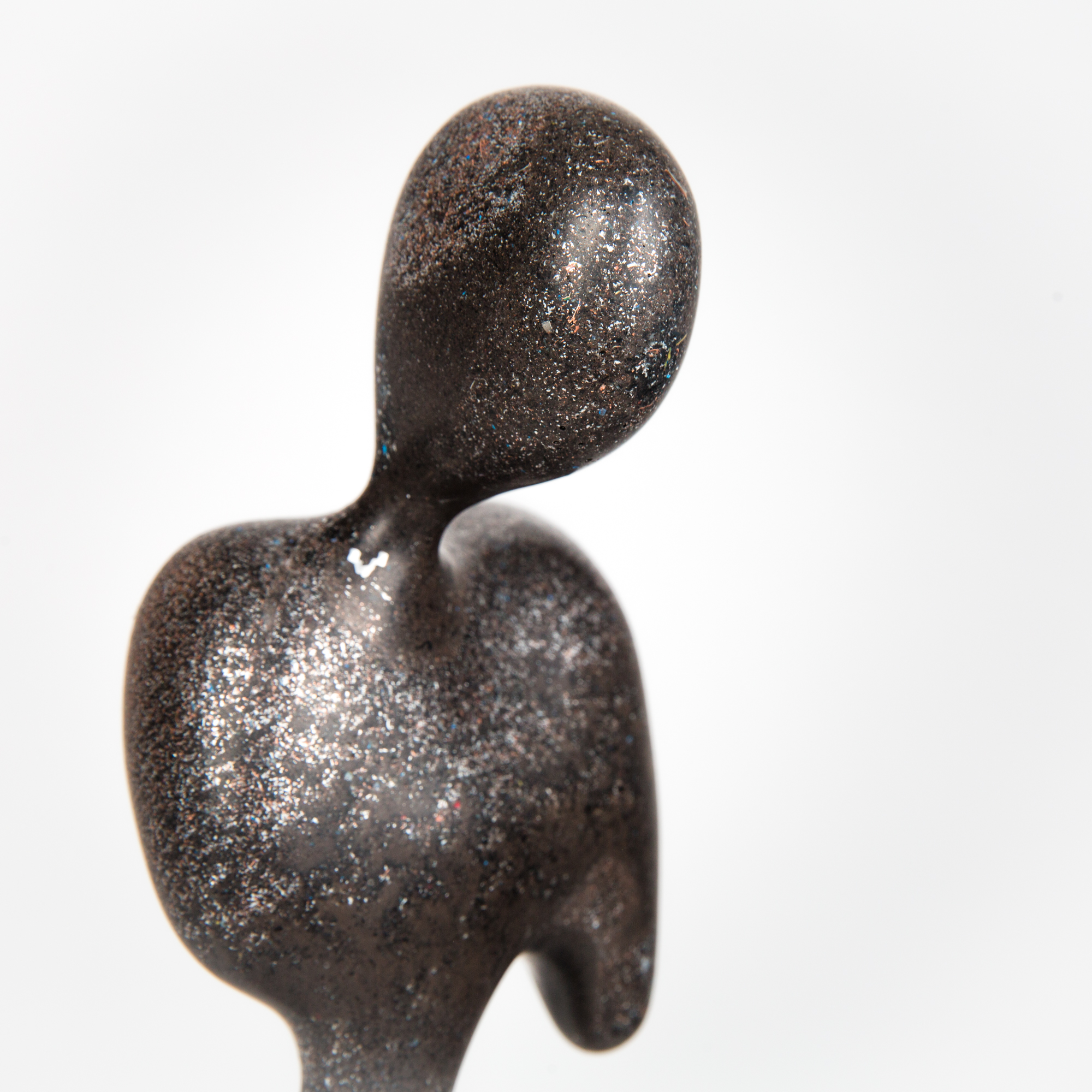
Although this form does not have any function from their physical existence, it manifests the sharp details that the artist puts in the artwork. In the photo above, you can see how the voxel-based 3D printer prints the exact form of the blood vessels within the brain structure with specific gradient shades. From evaluating the visual features that would be produced from the data to converting these materials to a readable format for the printer, artists use this type of 3D printing that brings the artwork that is usually visualized in screen to a physical form that gives life to the final form of their aesthetic sensibilities.

This project is an advancement in their 3D printing technology. Thus, each of their works doesn’t have a specific title. Also, as read from the article, this project was initiated and completed in a group of MIT media lab workers.

Eunice Choe – Looking Outwards-03

The dome in the process of being built. The structure was printed in 13.5 hours.

The DCP uses robotic arms to build the structure.

The Hemi-ellipsoidal Dome (2016/ongoing) is a 3D printed structure that was fabricated using the Digital Construction Platform by Mediated Matter. I admire this architectural structure because it shows that 3D printed technology can be used for large-scale structures as well as small scale structures. I admire Mediated Matter’s ability to solve problems while stretching the bounds of an existing technology. For instance, this structure was created using a Print-in-Place construction technique which prints molds of structures and has the potential to use materials, time, and money more efficiently. Regarding the algorithms used to build the structure, the dome uses the Print-in-Place technique and the Digital Construction Platform, which is a technology that utilizes robotic arms to construct the building. This technology has developed over time to be more sensitive to real time feedback and the mobility of the arms. The designers’ artistic sensibilities are evident in the dome, as seen through their inspiration from the geometry and form of a hemi-ellipsoid. Other structures built from this technology can show glimpses of creative architectural freedom because it can rapidly create non-traditional structures like the dome, which was printed in 13.5 hours.

Jenna Kim (Jeeyoon Kim)- Project 3- Dynamic Drawing

jennakim03

/* Jenna Kim (Jeeyoon Kim)
Section E
jeeyoonk@andrew.cmu.edu
Project 03
*/

var xpan = 200;
var ypan = 130;
var panWidth = 145;
var panHeight = 83;
var xhandle = 44;
var yhandle = 120;
var handleWidth = 84;
var handleHeight = 12;

var xegg = 200;
var yegg = 87;
var eggWidth = 71;
var eggHeight = 100;

var xnewpan = 456; 
var ynewpan = 324;
var newpanWidth = 277;
var newpanHeight = 161;
var newxhandle = 155;
var newyhandle = 320;
var newhandleWidth = 164;
var newhandleHeight = 24;

var angle1 = 6;
var distance = 0.1;

function setup() {
    createCanvas(640, 480);
}


function draw() {
	//background color "change" when you move the cursor
	background(234, 210, 249);
	colorMode(RGB);
	R = (mouseX / width) * 255;
	G = (mouseY / width) * 255;
	var c = color(R, G, 200);
	background(c);

  //egg rotating around mouse
  noStroke(0);
  fill(255); //
  stroke(0);
  push();
  translate(mouseX, mouseY);
  rotate(radians(angle1));
  ellipse(50, 50, eggWidth, eggHeight);
  pop();
  angle1 = angle1 + 6;
  distance = distance + 0.1;

//when you drag to the right, the egg size increase!!
if (mouseX > 420) {
    eggWidth += 0.5;
    eggHeight +=0.5
}

	//if mouse is Pressed, Fried Egg appears (size change/position change)
if (mouseIsPressed) {
	//new pan drawing
	noStroke(0);
  	fill(114, 114, 114);
  	ellipse(xnewpan, ynewpan, newpanWidth, newpanHeight);
  	fill(94, 94, 94);
  	ellipse(xnewpan, ynewpan - 10, newpanWidth, newpanHeight);
  	rect(newxhandle, newyhandle, newhandleWidth, newhandleHeight);

  	//Fried Egg
  noStroke(0);
  	fill(256);
  	ellipse(456, 316, 160, 110);
  	fill(249, 183, 65);
  	ellipse(447, 306, 71, 42);
  } else {
	push();
  	//pan drawing
  	fill(114, 114, 114);
  	ellipse(xpan, ypan, panWidth, panHeight);
  	fill(94, 94, 94);
  	ellipse(xpan, ypan - 10, panWidth, panHeight);
  	rect(xhandle, yhandle, handleWidth, handleHeight);
  	pop();
}
  print(mouseIsPressed);

  textSize(17);
  fill(50);
  text('dancing egg', mouseX + 5, mouseY, 100, 100);

}

“DON’T FORGET TO PRESS THE CANVAS”

For this project, I put five interactions in total; swinging of the egg, egg transforming to another position, and size of the pan changing when mouse is clicked, egg size increasing slowly as the mouse moves to the right, and color change of the background when mouse is moved around the canvas. Through this project, I learned that there are so many different interactions you can do just by moving, dragging, clicking the mouse.

Looking Outwards 03: Under Armour

Instantly when prompted with the idea of generative design, I thought of Autodesk and the work they did with Under Armour to create the Architech shoe. With today’s tech and designer’s love of sneakers, it was inevitable that a mass market 3D printed shoe was going to hit the market.

The shoe sole is designed with the wearer in mind and provides a rather sensitive approach to footwear. When they developed the shoes, they weren’t just trying to showcase the tech, but also took into account the user experience of it all.

They began in Fusion360 and generated the structures, they used Autodesk’s Myriad program to create the pattern of cells. The advantage of using Myriad was that they were able to test out many variations of spacing and design till they arrived at their final result.

I like reading about tech and the role it playsinto product design because alot of conceptual artwork exists with tech, but taking the concepts and finding a practical application can change so many things in industry.

Rachel Lee-Project 03-Dynamic Drawing-Section E

Rachel Lee Dynamic Drawing Sketch

/* Rachel Lee
rwlee
Section E
Project-03: Dynamic Drawing */

var outerD = 350;
var innerD = 300;
var hours = 10;
var r = 0;
var g = 0;
var b = 0; 
var planetR = 60;
var sunY = 0;
var moonY = 480; 
var angle = 0;
var increment = 0.1;
var angle = 0;
var position1 = 0;
var position2 = 105;
var position3 = 65;
var position4 = 215;
var position5 = 25;
var position6 = 345;

function setup() {
    createCanvas(640, 480);
}

function draw() {
	background(r, g, b);
// top right quadrant yellow according to mouse position
    if (mouseX >= 320 & mouseX <= 640 && mouseY >= 0 && mouseY <= 240) {
        r = 235;
        g = 200;
        b = 130; 
    } 
    
// bottom right quadrant pale blue according to mouse position
    if (mouseX >= 320 & mouseX <= 640 && mouseY >= 240 && mouseY <= 480) {
        r = 155;
        g = 195;
        b = 235;
    }
// bottom left quadrant dark blue according to mouse position
    if (mouseX >= 0 & mouseX <= 320 && mouseY >= 240 && mouseY <= 480) {
        r = 30;
        g = 115;
        b = 185;
    }
// top left quadrant navy according to mouse position
     if (mouseX >= 0 & mouseX <= 320 && mouseY >= 0 && mouseY <= 240) {
        r = 15;
        g = 65;
        b = 120;
    }

    // sun rising and setting according to mouse position
    if (mouseX >= 330 & mouseX <= 500 && mouseY >= 65 && mouseY <= 415) {
        sunY = mouseY;
        var sizeSun = map(mouseY, 0, width, 60, 10);
    } else {
        noStroke();
        fill(240, 150, 60);
        sunY = 0;
        ellipse(560, sunY, planetR, planetR);
    }

// drawing sun
    noStroke();
    fill(240, 150, 60);
    ellipse(560, sunY, sizeSun, sizeSun);

// moon rising and setting according to mouse position
    if (mouseX >= 150 & mouseX <= 310 && mouseY >= 65 && mouseY <= 415) {
        moonY = mouseY;
        var sizeMoon = map(mouseY, 0, width, 60, 10);

// drawing stars
        push();
        translate(100, 100);
        rotate(radians(angle));

// animating stars, stars appear when it is 'night time' only
        rectMode(CENTER);
        noStroke();
        fill(210, 240, 245);
        rect(position1, 0, 15, 15);
        rect(position2, 125, 20, 20);
        rect(position3, 300, 10, 10);
        rect(position4, 240, 7, 7);
        rect(position5, 160, 13, 13);
        rect(position4, 270, 9, 9);
        pop();
        angle = angle + 1;
        position1 = position1 + 0.4;
        position2 = position2 - 0.1;
        position3 = position3 + 0.7;
        position4 = position4 - 0.2;
        position5 = position5 + 0.1;
        position6 = position6 - 0.8;

    } else {
        noStroke();
        fill(230, 230, 190);
        moonY = height;
        ellipse(80, moonY, planetR, planetR);
    }

// drawing moon
    noStroke();
    fill(230, 230, 190);
    ellipse(80, moonY, sizeMoon, sizeMoon);

// clock and hour markers on clock
    noStroke();
    fill(140, 195, 200);
    ellipse(320, 240, outerD, outerD);
    fill(180, 225, 225);
    ellipse(320, 240, innerD, innerD);

    fill(220, 90, 95);
    ellipse(320, 110, hours, hours);
    ellipse(320, 365, hours, hours);
    ellipse(180, 240, hours, hours);
    ellipse(450, 240, hours, hours);

// clock hands rotate according to mouse position
    stroke(255);
    strokeWeight(10);
    line(width/2, height/2, mouseX, mouseY); // minute hand
    stroke(0);
    line(width/2, height/2, mouseX + 40, mouseY + 60); // hour hand


}


For this week’s project, I decided to play with the idea of a clock, and illustrating different times of the day. At first I found it a little tricky to catch syntax errors, but as I built more and more variables in, it became really fun to watch my dynamic drawing come to life in a controlled manner.

Emily Zhou –– Dynamic Drawing

Moving the mouse to the right side of the frame will draw a colour-changing spiral. Move the mouse to the left side of the frame will erase the spiral.

sketch

// spiral variables:
var angle = 0;
// position parameter
var circleX = 25;
// to keep track of circles
var counter = 0;
// color parameter
var R = -100;
var G = 200;
var B = 20;
// calculation: 360 degrees / 5 degree angle change
var CIRCLES_PER_ROUND = 360 / 5;

function setup() {
    createCanvas(640, 480);
    background(0);
}

function draw() {

    // spiraling colored circles

    // to limit circle size of spiral
    if (counter < 25 * CIRCLES_PER_ROUND) {
        push();
        translate(320, 240);
        rotate(radians(angle));
        // stroke overlap creates smaller circles toward center
        // (size parameter)
        stroke(0);
        // RGB used in color parameter
        fill(R + ((counter - CIRCLES_PER_ROUND) / 8), 
             G - ((counter - CIRCLES_PER_ROUND) / 8),
             B + ((counter - CIRCLES_PER_ROUND) / 8));
        // circleX used in position parameter
        ellipse(circleX, 0, 5, 5);
        pop();
        if (mouseX > width / 2) {
            circleX = circleX + 0.1;
            angle = angle + 5;
            // circle is drawn on every count
            counter = counter + 1;
        }
    }
    
    // spiraling black circles 
    // (opposite direction to "erase")

    // to prevent spiral in opposite direction
    if (counter > 0) {
        push();
        translate(320, 240);
        rotate(radians(angle));
        stroke(0);
        fill(0);
        // circleX used in position parameter
        ellipse(circleX, 0, 7, 7);
        pop();
        if (mouseX < width / 2) {
            // circles drawn counterclockwise
            circleX = circleX - 0.1;
            angle = angle - 5;
            // to keep track of last colored circle
            counter = counter - 1;
        }
    }


    // smiley face

    var m = max(min(mouseX, 640), 0);
    // used in angle parameter
    var angleSmile = m * 640 / 360;

    // yellow circle
    fill(255, 230, 0);
    ellipse(width / 2, height / 2, 50, 50);
    // mouth
    strokeWeight(1.5);
    push();
    translate(320, 240);
    rotate(radians(angleSmile));
    arc(0, 0, 35, 35, 0, PI);
    pop();
    angleSmile = angleSmile + 5;
    // L eye
    fill(0);
    push();
    translate(320, 240);
    rotate(radians(angleSmile));
    ellipse(-8, -7, 3.5, 7);
    pop();
    angleSmile = angleSmile + 5;
    // R eye
    fill(0);
    push();
    translate(320, 240);
    rotate(radians(angleSmile));
    ellipse(8, -7, 3.5, 7);
    pop();
    angleSmile = angleSmile + 5;
    
}

I had some trouble with this project. I started with this idea in mind but realized pretty late into the game that the spiral drawing required background() to be under setup() but adding size parameters required it to be under draw(). I eventually found another way using stroke() but it still limited the graphics. Setting color parameters was also difficult since it was hard to predict; I ended up just experimenting with random values.

Eliza Pratt – Project-03

sketch

/* 
Eliza Pratt
Section E
elpratt@andrew.cmu.edu
Project-03
*/

function setup() {
    createCanvas(640, 480); 
}

function draw() {
    
    noStroke();

    //creates color variables for background based on mouse position
    var bG = (mouseX/width) * 255;
    var bB = (mouseY/height) * 255;
    background(100, bG, bB);

    //block of color that moves with mouseX
    fill(200, bG, bB);
    rect(0, 0, mouseX, 480);

    //starting positions for vertical and horizontal lines
    var y1 = 45;
    var x1 = 0;

    //variables for line weight and angle based on mouse position
    var hWidth = (mouseY/width) * 45 
    var angle = (mouseX/width) * 360
    fill(255);


    ////////ROTATING LINES///////
    push();
    //transforms vertical lines to rotate about the center
    translate(width/2, height/2);
    rotate(radians(angle));
    //draws vertical lines
    for(var i = 0; i < 20; i++) {
        fill(0);
        rect(x1 -50 - width/2, 0, hWidth, 800);
        x1+=50;
    } 
    pop();

    /////////HORIZONTAL LINES////////
    for(var i = 0; i < 9; i++) {    
        rect(width/2, y1, width, hWidth);
        y1+=50;
    } 

    
}

Compared to the last two weeks, I found this project to be the most challenging since it was so open ended. While this sketch was originally intended to be a grid with fixed horizontal and rotating vertical lines, I ended up with this just by commenting out the “recMode(CENTER) and letting the black lines do as they please! This turned out way cooler than I expected and I was pleasantly surprised with how the colors go together.

Jenny Hu — Looking Outwards 03

 Dio (Consummation) is a sculpture by Ben Snell, an artist based in Queens and a recent graduate of Carnegie Mellon. What I admire most about this work is actually the poetic process and perspective Ben takes. The first paragraph really says it all:

“Dio is the name of my computer. I trained it to study classical sculpture, then asked it to close its eyes and dream of a new sculpture—one which has never before been seen. Then, I ground Dio to dust and re-formed it into its dream. This sculpture is both the computer and the computer’s dream.”

This piece was generated by an algorithm, but he doesn’t go into its specifics. Instead, we’re asked to think about the algorithm as the computer’s dream, thoughts that it owns.

Jenny Hu — Dynamic Drawing

jenny’s dynamic drawing

//Jenny Hu
//Section E
//jjh1@andrew.cmu.edu
//Project 03 — Dynamic Drawing


var x1 = 320; //center of first ellipse
var y1 = 240;

var x2 = 50; 
var y2 = 240;

var x3 = 590; 
var y3 = 240;

var maxEllipse = 50;

var startD = 10; // starting diameter 
var R = 255; 
var G = 0; 
var B = 110; 

var bR = 0;
var bB = 0;

var rippleHappening = false;
var whereIsRipple = 0;//this is the number that controls where 
//the ripple is relative to the center
function setup() {
    createCanvas(640, 480);
    ellipseMode(CENTER); 
}


function draw() {
    //making background color variable
    bR = mouseX;
    bB = mouseY;
    background(bR,bB,100); 

    //Draw the ellipses
    for ( var i=0; i<maxEllipse; i++){
      noFill();

      //ellipse positions
      var x2 = mouseY - 10;
      var x3 = (width/2) - (x2-(width/2)); //make x3 move opposite of x2
      var y2 = mouseX + 10;
      var y3 = (height/2) - (y2-(height/2)); //mover y3 opposite of y2
      
      //making a ripple
      if(rippleHappening){
        //print("in the for loop?");
        if(i == int(whereIsRipple)){
          strokeWeight(6);
        }else{
          strokeWeight(2.25);
        }
      }else{
        strokeWeight(2.25);
      }


      var scale1 = (width/2-mouseX)/10; //all scale variables are to scale the space between ellipses
      var scale2 = (width/2-mouseX)/10;
      var scale3 = (width/2-mouseX)/10;

      R = mouseX;
      G = mouseX - (mouseX/2);
      B = mouseY - (mouseX/2);

      stroke(R, G, B);

      ellipse(x1,y1, startD+(i*scale1), startD+(i*scale1)); //center ellipse 
      ellipse(x2,y2, startD+(i*scale2), startD+(i*scale2)); //starting left ellipse
      ellipse(x3,y3, startD+(i*scale3), startD+(i*scale3)); //starting right ellipse

    }
    //whereIsRipple determines the ripple ellipse per set of rings 
    //if we mod the ripple, we limit it to how far the ripple goes
    whereIsRipple = (whereIsRipple+0.5)%maxEllipse;
    if(int(whereIsRipple) == (maxEllipse)){
      print("is rippleHappening turned false?");
      //turn boolean to false 
      rippleHappening = false;
    }

}
function mousePressed(){
  rippleHappening = !rippleHappening;
  whereIsRipple = 0; //start ripple at 0

}


I started this project with the intention to play with moire patterns, which is essentially patterns that come about when you overlap striped elements on top of one another (made by the gaps between the stripes). I think this was the most fun project so far because I was generated outputs I couldn’t have made without a lot more effort in other programs. It was a result that was more easily achievable via programming.

Originally, I planned the ellipsis in sketch, just to see the starting pattern, but everything else resulted from playing with the program.

You can click anywhere on the canvas to cause a continuous ripple across the ellipsis. I imagine that this can go with music one day to make a great audio visualizer! (perhaps my final project?)

special thanks to Marisa Lu, and Gautam Bose for the help.

Eliza Pratt – Looking Outwards 03

Elona Van Gent’s sculpture featured in Out of Hand , a NYC exhibit on “Materializing the Postdigital”

Elona Van Gent’s 3D printed sculpture, Wheelclawsteeth, demonstrates how digital fabrication can be used to create works that replicate naturally occurring or handmade forms. With the use of a Laminated Object Manufacturing machine (or LOM), Elona crafts “alluring and discomforting creatures” with laser-cut paper. Not only do I find her work captivating in a Guillermo-del-Toro-like fashion, but I deeply admire Van Gent’s ability to push the boundaries of computer generated sculptures to create work that could not exist in an art world void of technological advancements. By developing sculptures that appear naturally grotesque with the use of machinery, Elona challenges the existing polarity between digital fabrication and traditional sculpture. I find this to be a commendable objective in a climate where computer generative art is regarded as separate and distinctive from hand-crafted sculptures and installations.