Project-03 Dynamic Drawing

dynamic
function setup() {
    createCanvas(600, 450); 
    background(220);
    text("p5.js vers 0.9.0 test.", 10, 15);
}

function draw() { 
	background(0);
	noStroke();
	//boxes coming in from the right 
	fill(mouseY, 0, mouseX);
    rect(0, 0, mouseX, 50);
    fill(0, mouseY/2, mouseX/2);
    rect(0, 100, mouseX, 50);
    fill(mouseY/3, 0, mouseX/3);
    rect(0, 200, mouseX, 50);
    fill(0, mouseY, mouseX);
    rect(0, 300, mouseX, 50);
    fill(mouseY/2, 0, mouseX/2);
    rect(0, 400, mouseX, 50);

    //boxes coming in from the left 
    fill(255-mouseY, 0, 255-mouseX);
    rect(600, 50, -mouseX, 50);
    fill(0, 255-mouseY/2, 255-mouseX/2);
    rect(600, 150, -mouseX, 50);
    fill(255-mouseY/3, 0, 255-mouseX/3);
    rect(600, 250, -mouseX, 50);
    fill(0, 255-mouseY, 255-mouseX);
    rect(600, 350, -mouseX, 50);

    //boxes coming in from the top 
    fill(255-mouseY, 0, 255-mouseX);
    rect(0, 0, 50, mouseY);   
    fill(0, 255-mouseY/2, 255-mouseX/2);
    rect(120, 0, 50, mouseY); 
    fill(255-mouseY/3, 0, 255-mouseX/3);
    rect(240, 0, 50, mouseY);   
    fill(0, 255-mouseY, 255-mouseX);
    rect(360, 0, 50, mouseY);
    fill(255-mouseY/2, 0, 255-mouseX/2);
    rect(480, 0, 50, mouseY);

    //boxes coming in from the bottom 
    fill(mouseY, 0, mouseX);
    rect(60, 600, 50, -mouseY);  
    fill(0, mouseY/2, mouseX/2);
    rect(180, 600, 50, -mouseY);   
    fill(mouseY/3, 0, mouseX/3);
    rect(300, 600, 50, -mouseY);   
    fill(0, mouseY, mouseX);
    rect(420, 600, 50, -mouseY);
    fill(mouseY/2, 0, mouseX/2);
    rect(540, 600, 50, -mouseY);

    //moving origin point to the center 
    translate(300, 225);

    //rect & all ellipses rotate based on mouse 
    rectMode(CENTER);
    rotate(radians(mouseX));
    rect(0, 0, 100, 100);

    //ellipses change position based on mouse 
    ellipse(-100, mouseX, 30, 30);
    ellipse(mouseX, -100, 30, 30);

    //ellipses get bigger based on mouse 
    stroke(255);
    strokeWeight(3);
    noFill();
    ellipse(0, 0, mouseX, mouseY);
    stroke(100);
    ellipse(0, 0, -mouseX, mouseY);
    //rotated ellipses  
    rotate(radians(45));
    stroke(255);
    ellipse(0, 0, mouseX+20, mouseY);
    stroke(100);
    ellipse(0, 0, -mouseX+20, mouseY);

    rotate(radians(45));
    stroke(255);
    ellipse(0, 0, mouseX+50, mouseY);
    stroke(100);
    ellipse(0, 0, -mouseX+50, mouseY);

    rotate(radians(45));
    stroke(255);
    ellipse(0, 0, mouseX+90, mouseY);
    stroke(100);
    ellipse(0, 0, -mouseX+90, mouseY);
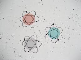
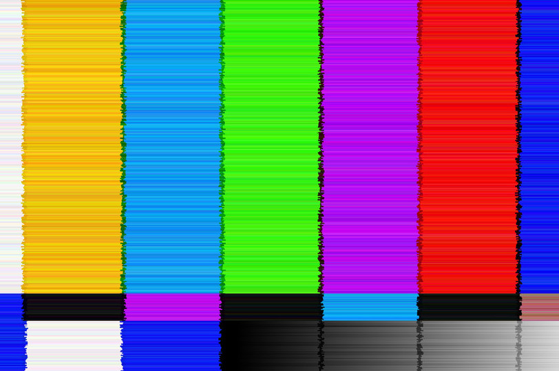
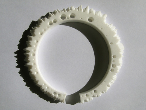
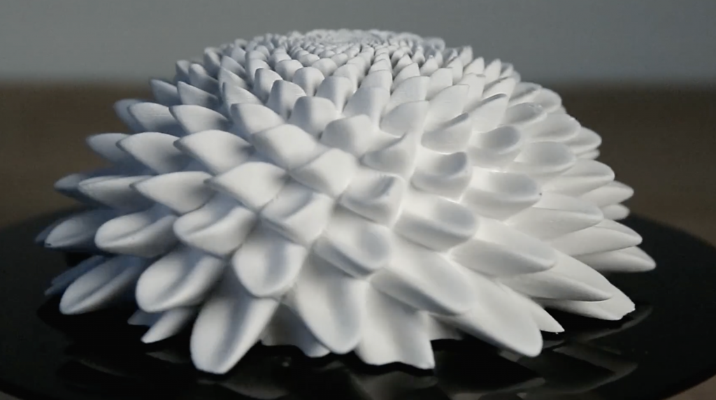
}

I was inspired by the shape of atoms. For the background, I was partly inspired by the way a tv looks when it glitches.

Inspiration image
Background inspiration image

LO-03 Computational Fabrication

Process of creating “Digital Grotesque”

Benjamin Dillenburger and Michael Hansmeyer and their team created “Digital Grotesque” in 2013. They used algorithmically generated geometry and additive manufacturing to create 260 million individually specified surfaces. The final product was 3.2 meters tall and used 11 tons of printed sandstone.

I admire the depth and form of this piece. From a distance the piece looks closed off but the closer you get to it the more details are revealed. Their effective use of perspective draws the viewers in. The artists are able to create an immersive experience of computational art by allowing viewers to walk through the piece itself. I also admire how ornate and aesthetically pleasing the piece is.

Dillenburger and Hansmeyer’s artistic sensibilities are seen in the intricacy of their design. They wanted to highlight how there can be chaos in order which they successfully do by using symmetry and hierarchy to create balance in their detailed design.

Close up of details
Initial Sketch

Sources
http://benjamin-dillenburger.com/grotto/
https://vimeo.com/74350367

LO 3: Computational Fabrication

The Weather Bracelet
Display of the Weather Bracelet

Creating the Weather Bracelet, Mitchell Whitelaw used generative design to translate the weather-data of Canberra, Australia into a fascinating jewelry piece. The height of each spike on the bracelet represents its daily maximum temperature, and the height of each spike’s shoulder represents its daily minimum. Generally, data visualization is seen in 2d form–whether it be graphic or motion graphic. However, Whitelaw’s work visualizes data as something physical as well as visual. By portraying data through an object–also known as autographic visualization–Whitelaw’s work is eye-opening and captivating.  In addition to its interesting process, the final work, the bracelet itself, is intrinsically beautiful. The uneven spikes and holes provide the bracelet with complexity and a futuristic look, balancing well with its minimalistic white color. 

Whitelaw accomplished most of his work by first defining a set of 3D points using beginShape() and vertex() and PVectors. To save the geometry of his object, he also used the SuperCad library to write an obj. file. He then worked in MeshLab and Blender to 3D model his bracelet before printing it out.

By utilizing the power of computation, Whitelaw was able to create a jewelry piece that is scientifically meaningful as well as personally meaningful. While making weather data tangible visually and physically, the bracelet also established a personal relationship with the wearer through the sense of touch. It facilitates an exciting experience as the wearer runs his or her fingers down the bracelet, reminiscing about the memories of different seasons and weather. 

Creator: Mitchell Whitelaw

Title: The Weather Bracelet

Year: 2009

Link: http://teemingvoid.blogspot.com/2009/10/weather-bracelet-3d-printed-data.html

Project 3 – Dynamic Drawing

sketch


function setup() {
    createCanvas(400, 400);
    rectMode(CENTER);
}

function draw() {
    background(30, 30, 40);
    noStroke();
    translate(200, 200);
    let angle = mouseY;
    rotate(radians(angle));
    //rectangle
    translate(-200, -200);
    fill(221, 115, 115);
    var m = max(min(mouseX, 400), 0);
    var size = m * 350.0 / 400.0;
    rect(10 + m * 190.0 / 400.0, 200.0,
         size/2, size/2);
    fill(234, 217, 76);
    size = 350 - size;
    rect(200 + m * 190.0 / 400.0, 200.0,
         size/2, size/2);
    //circles
    fill(209, 209, 209);
    var m = max(min(mouseY, 400), 0);
     var size = m * 350.0 / 400.0;
    circle(10 + m * 190.0 / 400.0, 200.0,
         size/2);
    fill(81, 163, 163);
    size = 350 - size;
    circle(200 + m * 190.0 / 400.0, 200.0,
         size/2);
    //small circle
    var m = min(min(mouseX, 400), 0);
    var size = m * 350.0 / 400.0; 
    fill(100, 178, 200);
    size = 250 - size;
    circle(m * 190.0 / 400.0, 200.0,
         size/10);
    //small circle pink
    var m = min(min(mouseX, 400), 0);
    var size = m * 350.0 / 400.0; 
    fill(240, 178, 200);
    size = 250 - size;
    circle(width - (m * 190.0 / 400.0), height - (200.0),
         size/10);
    //vertex circles
     fill(59, 53, 97);
    var m = max(min(mouseY, 400), 0);
     var size = m * 350.0 / 400.0;
    circle((10 + m * 190.0 / 400.0) + 100, (200.0) + 100,
         size/5);
    fill(196, 224, 249);
    size = 350 - size;
    circle((200 + m * 190.0 / 400.0) - 100, (200.0) - 100,
         size/5);
    //other vertex circles
     fill(171, 73, 103);
    var m = max(min(mouseY, 400), 0);
     var size = m * 350.0 / 400.0;
    circle(width - ((10 + m * 190.0 / 400.0) + 100), height - ((200.0) + 100),
         size/5);
    fill(173, 246, 177);
    size = 350 - size;
    circle(width - ((200 + m * 190.0 / 400.0) - 100), height - ((200.0) - 100),
         size/5);

}

I was inspired by random movements of shapes and the pattern that could be formed from it. The color palette was a big factor in this project.

Computational Fabrication

I admire Andrew Kudless‘s collaborative idea of nature and the computational form that is shown in the picture of “C_Wall” / 2006. When I look at this picture, I think it is interesting to see how natural wave-like circular patterns are created from the shadow of the sun, coming from the physical sculpture. I feel like the artist generated this work from nature like coral reef/honeycomb/etc something that is repetitive but not artificially but naturally created structural forms. Looking at the final forms(including other works) the Voronoi algorithm that the creator used, is successfully displayed to facilitate the translation of information from simulations and other point-based data. I think the creator created the perfect harmony of nature/man-made physical-forms considering how to express the materialization aspects at the same time.

“C_Wall”
“C_Wall”

LO 03 – Computational Fabrication

John Edmark

Blooms: Strobe-Animated Sculptures


Blooms: Strobe-Animated Sculptures

Today, I will be taking a look at John Edmark’s 3D printed sculpture, Bloom. These sculptures are designed to animate when spun under a strobe light. The animation is achieved by progressive rotations of the golden ratio. This project caught my attention because it is mostly inspired by nature, through his use of the golden ratio which can be found in pinecones and sunflowers. The sculpture is satisfying to look at, but also very discomforting at the same time. The movement and flexibility from a plastic object is very provocative and unexpected. I believe that the author used some sort of an intricate variable system to map out the shapes before 3D printing. The creator’s artistic sensibilities are present in the final form not only through the visually appealing outcome, but also his careful and intentional use of scale, and proportions to create these kinetic sculptures. 

View portfolio here

Blooms: Strobe Animated Sculptures

Looking Outwards 03: Computational Fabrication, SectionC

3D render of physical robot

A project I found to be inspirational was a project done by ALLAN ZHAO, JIE XU, MINA KONAKOVIĆ-LUKOVIĆ, JOSEPHINE HUGHES, ANDREW SPIELBERG, DANIELA RUS, and WOJCIECH MATUSIK, called RoboGrammar. This project is an approach to generate different robot structures that is able to move along various terrains. This project is admirable because they were able to come up with a small set of rules that can describe the hundreds and thousands arrangements of physical robot assemblies. While the rules or grammar supports many types of physical arrangements, it also limits the design space to designs that can be physically produced. I thought this related to programming because through assembling a code that supports the randomness of the variations while also setting limitations, a rule is formed that the project follows. 

https://cdfg.mit.edu/publications/robogrammar-graph-grammar-for-terrain-optimized-robot-design

Looking Outwards 3: Computational Fabrication

Laser cut fabric and wood

The project that I chose to highlight actually belongs to another CMU student –David Perry. It was interesting being able to see his project come to fruition throughout the Lunar Gala preparation process. More recently, I was able to interview him about the details and craftsmanship behind his line. During the interview, David talked about how his background in physics was able to help him develop the algorithms to laser cut the various materials and fabrics he used to construct his clothing line.

David Perry’s Scuba Helmet for Lunar Gala 2020

His most famous piece is this scuba diving helmet shown below. The whole product was visualized in CAD before each piece was individually laser cut and eventually put together (systematically) by hand. What I think is so amazing about this clothing line is how he draws together 2 disciplines to create wearable art inspired by the patterns of sea life.

Project 3-Many Squares

yeung-squaresDownload
var x;
var y;
var r=0;
var g=0;
var b=0;
var xtrans=300;
var ytrans=225;

function setup() {
    createCanvas(600, 450);
    background(0);
}

function draw() {
    var dir=mouseX * 1.5;
    x=mouseX;
    y=mouseY;
    translate(xtrans, ytrans);
    r=mouseY; //makes color change with mouse movements
    g=255-mouseY;
    b=mouseX;
    fill(r, g, b);
    var m = max(min(mouseX, 400), 0);
    var size = m * 350.0/400.0;
    rotate(radians(dir));
    rectMode(CENTER);
    var n = max(mouseX, 400);
    rect(x + m * 190.0/400.0, y + m * 190.0/400.0, m, m); //the two rectangles are opposites, one is big when the other is small
    rect(-(x + n * 190.0/400.0), -(y + n * 190.0/400.0), n, n); //both sizes of rectangles depend on mouse
    if (mouseIsPressed) { //moves the origin to mouseX and mouseY when mouse is pressed
        xtrans = mouseX;
        ytrans= mouseY;

    }
}

I like squares.

Looking Outwards 03: Computational Fabrication

Iris Van Herpen is an innovative fashion designer who has dressed some of the biggest stars in Hollywood, including Lady Gaga, Solange, and Katy Perry. Her designs are unique because she is constantly creating new materials and pushing the boundary of what fashion is. The collection I’m looking at is “Shift Souls,” which she unveiled in January, 2019 during Paris Fashion Week. The specific piece I’ll be talking about is “Cellchemy” face jewelry that was created in collaboration with Delft University of Technology.

Look 08, Shift Souls

I admire this piece because Van Herpen is constantly trying to reinvent the definition of fashion, and the piece is not only beautiful, but extremely intriguing when you realize what’s behind it. They used Grasshopper 3D to develop a generative design process based off of a 3D face scan, which was then combined with color information. This mapped a structure which resembled the face and worn as a mask. Van Herpen’s vision for this collection was based around advancements in DNA engineering which created the first human/animal hybrid. She confronts the unclear implications of the reality that we now have to address. The idea is manifested in “Cellchemy,” because the mask represents hybridity by creating lace-like masks of the human face that look animalistic.