Min Ji Kim Kim – Looking Outwards – 04

Video Demonstration of the Weather Thingy created by Adrien Kaeser at ECAL.

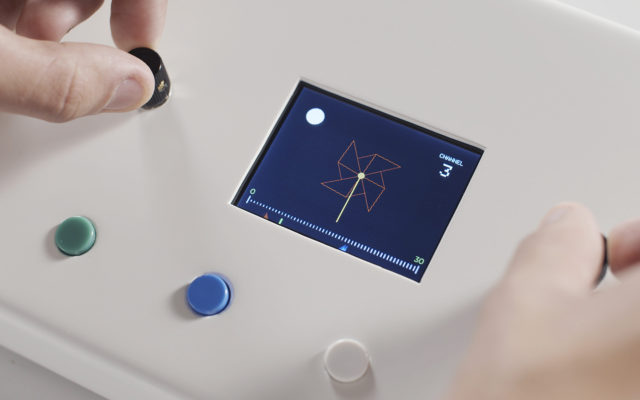
Weather Thingy, created by Adrien Kaeser at ECAL in September 2018, is a sounds controller that takes live climate data to modify the sounds of musical instruments. There are two parts to this device. The tripod microphone includes a wind vane, controlling pan, an anemometer, controlling the LFO, and a rain gauge, controlling the chorus. All of these parts are connected to the main controller with which the composer can manipulate these different elements. Through the Weather Thingy, Kaeser wanted to aurally share with the audience his live source of inspiration and how climate impacted his musical compositions. Software used to create the Weather Thingy include Arduino, C++ and MIDI protocol.

Controller interface of the anemometer input measuring wind speed.

I found this project to be astounding because, having composed music myself, sometimes I wish I could share my sources of inspiration and really let my audience visualize the atmosphere in which I wrote a song in. The Weather Thingy combines musical composition with natural elements in the environment and seeing how Kaeser wasn’t only able to get inspiration from nature but also incorporate nature directly into his compositions, is something I found really refreshing.

Weather Thingy – Real time climate sound controller

Looking Outward 03 – Ilona Altman

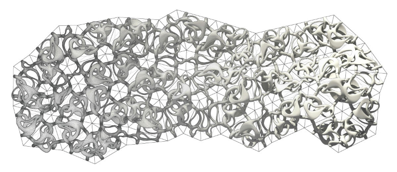
Polymorph project plan
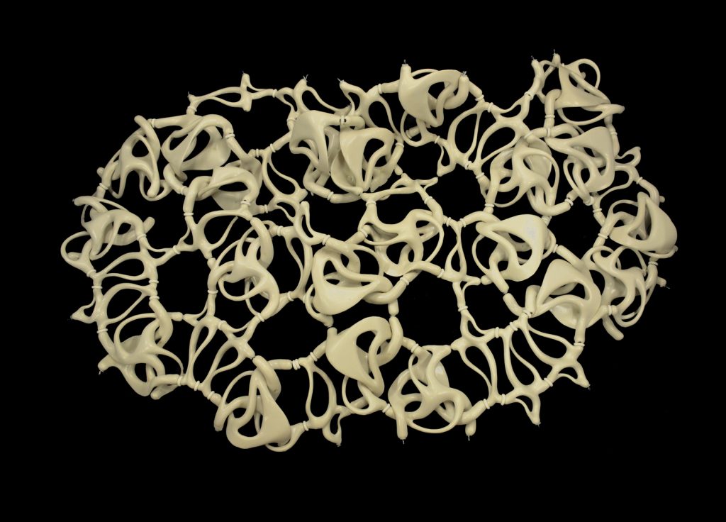
Polymorph project model
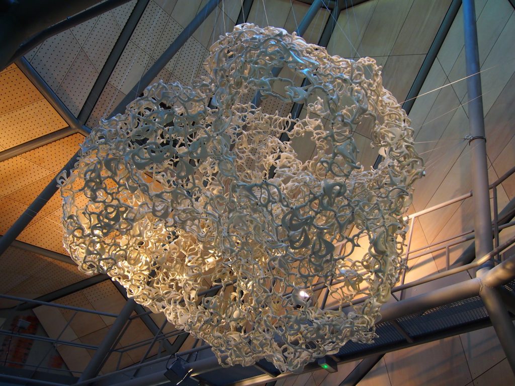
installation shot

I am really interested in the Polymorph project by the artist Jenny Sabin. This project is especially interesting because of how she combined form and function. The structure is made of clay and was digitally fabricated. The sculpture is rooted an algorithmic process that formulates the way that the ceramics are formed, fired and connected.

This piece of work is also interesting in how it uses natural structured in order to build it own structure, that this work could only be created aided with technology. As Jenny Sabin writes:  Biology provides useful systems-based models for architects to study and understand how context specifies form, function, and structure. While the first phase of this design work resides within the spirit of research and discovery, the current phase engages design-oriented applications in experimental ceramic material systems ranging from new concepts of materiality to adaptive structures and complex geometries. Key to this design research is the exploration of new tectonic organizations for application at the architectural scale. 

Here is a link to the project documentation and writing – http://www.jennysabin.com/polymorph-1

Hyejo Seo – Project-03: Dynamic Art


sketch

/* 
Hyejo Seo
Section A
hyejos@andrew.cmu.edu
Project-03- Dynamic Art
*/ 

var circleY = 250;  
var cSpeed = 1; 
var sunDia = 350;

function setup() {
  createCanvas(450,500);
}

function draw() {
    background(180, mouseY + 70, mouseY + 100);
//sun
fill(255, 100, 147);
noStroke();

if(mouseY >= 150){
  sunDia = 350; 
} else {
  sunDia = mouseY /2;
}
circle(225, 290, sunDia); 
  
//smoke 
    circleY = circleY - cSpeed; 
    fill(198, 207, 220);
    noStroke();
    circle(220, circleY, 100);
    if(circleY >= height){
      circleY = -cSpeed;
     } 
    circle(250, circleY, 90);
    if(circleY > height){  
      cSpeed = cSpeed;
     }
    circle(200, circleY + 70, 80);
    if(circleY + 70 > height){    
      cSpeed = cSpeed;
    }
    circle(250, circleY + 60, 100);
    if(circleY + 50 > height){    
      cSpeed = cSpeed;
    }
    circle(210, circleY - 50, 90);
    circle(260, circleY - 50, 100);
    if(circleY - 50 > height){
      cSpeed = cSpeed;
    } 
    circle(210, circleY - 100, 80);
    circle(250, circleY - 100, 90);
    if(circleY - 100 > height){
      cSpeed = cSpeed;
    } 
    circle(210, circleY - 80, 100);
    if(circleY - 50 > height){
      cSpeed = cSpeed;
    } 

    if(circleY <= -100){
      circleY = height;
    }
//Volcano
fill(234, 51, 28);
if(mouseY <= 150){
  beginShape();
  curveVertex(170, 500);
  curveVertex(170, 500);
  curveVertex(170, 280);
  curveVertex(90, 150);
  curveVertex(130, 150);
  curveVertex(150, 120);
  curveVertex(180, 145);
  curveVertex(220, 80);
  curveVertex(250, 150);
  curveVertex(280, 130);
  curveVertex(280, 170);
  curveVertex(290, 165);
  curveVertex(320, 150);
  curveVertex(380, 145);
  curveVertex(310, 250);
  curveVertex(330, 500);
  curveVertex(330, 500);
  endShape();
} else {
  endShape();
    beginShape();
    curveVertex(170, 500);
    curveVertex(170, 500);
    curveVertex(170, 280);
    curveVertex(310, 280);
    curveVertex(200, 500);
    curveVertex(200, 500);
    endShape();
}
// mountain
    fill (170, 140, 99);
    noStroke();
    quad(0, 500, 450, 500, 350, 350, 100, 350); 
    
// mountain peak
    fill(170, 140, 99);
    beginShape();
    curveVertex(100, 350);
    curveVertex(100, 350);
    curveVertex(140, 280);
    curveVertex(170, 250);
    curveVertex(210, 270);
    curveVertex(240, 260);
    curveVertex(270, 290);
    curveVertex(310, 250);
    curveVertex(350, 350);
    curveVertex(350, 350);
    endShape();

// mountain body detail 
    stroke(67,42, 29);
    strokeWeight(3);
    line(50, 500, 150, 300);
    line(140, 450, 190, 310);
    line(200, 490, 230, 300);
    line(250, 450, 245, 300);
    line(300, 500, 280, 320);
    line(350, 500, 300, 300);
}

For this project, I have created an interactive piece of a volcano explosion – from the moment of the lava boiling, which was depicted by the smoke to the explosion. I had fun and learned a lot experimenting with interactive/conditional functions. 
Min Ji Kim Kim – Project 03 – Dynamic-Drawing


sketch

I tried playing with a lot of different shapes, sizes and colors to create an abstract design. I had so much fun using mouseX and mouseY and manipulating them to get different effects.

/*
Min Ji Kim Kim
Section A
mkimkim@andrew.cmu.edu
Project-03
*/
var angle = 0; //angle used to rotate rectangle

function setup() {
    createCanvas(480, 640);
}

function draw() {
    noStroke();

    //change background color depending on mouseX position
    background(204, 255, 200);
    if (mouseX > width / 2) {
        background(170, 170, 230);
    }

    //navy rectangle
    fill(0, 76, 152);
    rectMode(CENTER);
    rect(width / 2, height / 2, mouseX, 200); //change rectangle width according to mouseX position

    //turquoise circle
    fill(0, 180, 159);
    circle(mouseY, mouseX, 80); //circle moves inversely to mouse

    //light blue circle
    fill(176, 211, 234);
    circle(300, 500, mouseY / 2); //expand or shrink circle by a factor of 1/2 depending on mouseY position 

    //light pink rectangle
    fill(245, 199, 231);
    rectMode(CENTER);
    rect(249, mouseY, 50, 100); //rectangle follows mouseY

    //salmon color rectangle translation and rotation
    push();
    translate(width / 3, 200);
    rotate(radians(angle));
    fill(250, 152, 167);
    rectMode(CENTER);
    rect(0, 0, 90, 90);
    pop();

    //mouseX controls salmon colored rectangle's rotation direction
    if (mouseX < width / 3) { //if mouseX is on the left 1/3 of the canvas, rotate anticlockwise
        angle = angle - 3;
    } else { //if mouseX is on the right 2/3 of the canvas, rotate clockwise
        angle += 3;
    }

    //small magenta circle 
    fill(110, 0, 70);
    ellipseMode(CENTER);
    ellipse(mouseX, mouseY, 35); //circle follows the mouse

    //orange rectangle
    fill(255, 178, 149);
    rect(mouseX, 380, 170, 25); //rectangle follows mouseX
}

Min Ji Kim Kim – Looking Outwards – 03


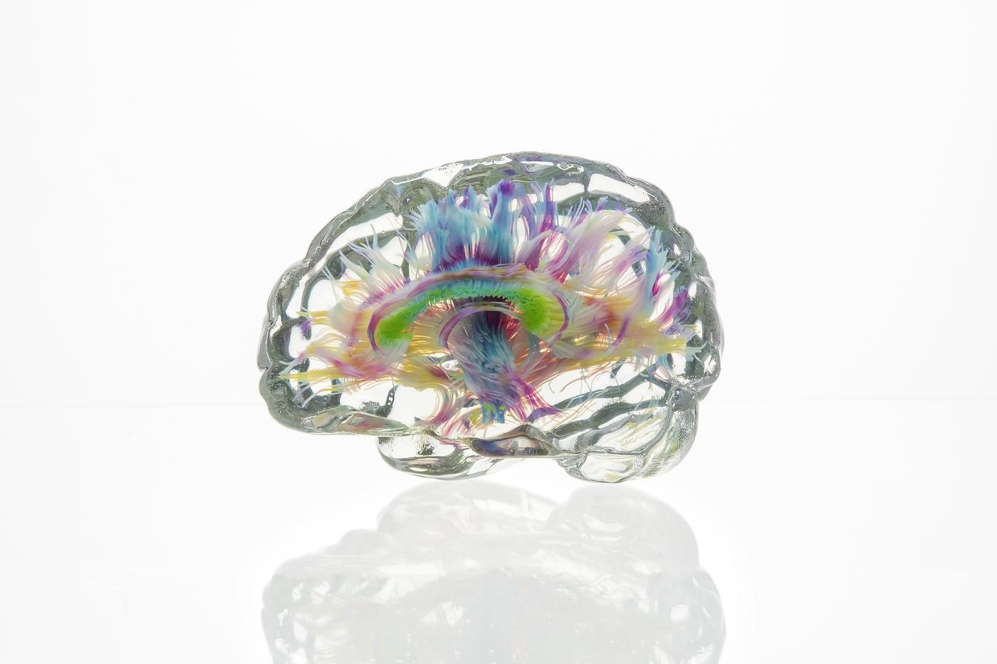
3D voxel-printed model of a human brain visualizing axon bundles. The Mediated Matter Group.

This model of the human brain was created through voxel-printing, which is a new 3D printing method created by MIT Media Lab’s Mediated Matter Group. Printing in voxels, which are the equivalent of 3D pixels, allows for much more precise renderings of the complex and fine details present in 3D computerized data. Further, it allows one to properly visualize any “floating” structures that aren’t directly connected to the body of the object. Before voxel-printing, 3D printing required a computerized model of the structure first, which often distorted images. With the availability of voxel-printing, 3D printed objects are now created in much higher definition.

Close-up of a voxel-printed 3D model of human lung tissue. The Mediated Matter Group.

I am fascinated by this recreation of lung tissue and how this new 3D printing method is able to capture the most fine and minute details, recreating computerized data into extremely accurate physical visualizations. Because voxel-printing can also print “floating” structures, computer models will no longer suffer a loss in quality when they’re physically brought to life. I believe that voxel-printing will improve the 3D printing industry and open doors for new ways of modeling and creating objects. 

https://www.media.mit.edu/projects/making-data-matter/overview/

Steven Fei – Project – 03


Steven Fei dynamic Drawing


function setup() {
    createCanvas(600, 480);
    
}

var size = 8; //hexagon size that can change according to the mouse movement
let color = 0; //hexagon color that can change according to the mouse movement
var colorDir = 2; //the degree of change for the color change
let angle = 0; //the initial rotation angle for the hexagon
var dir = 1; // the growing direction of the hexagon, either positive or negative
var speed = 2; //the growing speed of the hexagon

function mouseMoved(){
    color = color +colorDir;
    if (color<0){
        colorDir = 2;
    } else if (color>255){
        colorDir = -2;
    }
    angle +=0.6;
    size += dir * speed;
    if(size<0){
        dir = 1;
        size = 0;
    }else if (size>60){
        dir = -1;
        size = 60;
    }
}

var diffx = 0;
var diffy = 0;
var circlex = 300;
var circley = 300;

function draw() {
    background(0);
//    locate the mouse position
    diffx = mouseX - circlex;
    diffy = mouseY - circley;
    circlex = circlex + 0.1*diffx;
    circley = circley + 0.1*diffy;
    fill("white");
    circle(circlex,circley,20);
    
    fill(color,37,213);
    var x = max(min(mouseX,300),5); // decide the starting point of the hexagon, when the mouse is far on the left the canvas, the hexagons may shrink together and when the mouse is far on the right of the canvas, the hexagons may move away from each other
    translate(300,240); //move to the center of the canvas
//    draw the basic shape for 1st Hexagon  
    beginShape();
    rotate(radians(angle));
    vertex(x/2,0);
    vertex(x/2+size*cos(radians(60)),0-size*sin(radians(60)));
    vertex(x/2+size+size*cos(radians(60)),0-size*sin(radians(60)));
    vertex(x/2+size+2*size*cos(radians(60)),0);
    vertex(x/2+size+size*cos(radians(60)),size*sin(radians(60)));
    vertex(x/2+size*cos(radians(60)),size*sin(radians(60)));
    endShape();
    // draw the basic shape for 2nd Hexagon
    rotate(radians(60));
    beginShape();
    vertex(x/2+1.3,0);
    vertex(x/2+1.3+1.3*size*cos(radians(60)),0-1.3*size*sin(radians(60)));
    vertex(x/2+1.3+1.3*size+1.3*size*cos(radians(60)),0-1.3*size*sin(radians(60)));
    vertex(x/2+1.3+1.3*size+2*1.3*size*cos(radians(60)),0);
    vertex(x/2+1.3+1.3*size+1.3*size*cos(radians(60)),1.3*size*sin(radians(60)));
    vertex(x/2+1.3+1.3*size*cos(radians(60)),1.3*size*sin(radians(60)));
    endShape();
//    draw the basic shape for 3rd Hexagon
    rotate(radians(60));
    beginShape();
    vertex(x/2+1.5,0);
    vertex(x/2+1.5+1.5*size*cos(radians(60)),0-1.5*size*sin(radians(60)));
    vertex(x/2+1.5+1.5*size+1.5*size*cos(radians(60)),0-1.5*size*sin(radians(60)));
    vertex(x/2+1.5+1.5*size+2*1.5*size*cos(radians(60)),0);
    vertex(x/2+1.5+1.5*size+1.5*size*cos(radians(60)),1.5*size*sin(radians(60)));
    vertex(x/2+1.5+1.5*size*cos(radians(60)),1.5*size*sin(radians(60)));
    endShape();
//  draw the basic shape for 4th Hexagon
    rotate(radians(60));
    beginShape();
    vertex(x/2+1.7,0);
    vertex(x/2+1.7+1.7*size*cos(radians(60)),0-1.7*size*sin(radians(60)));
    vertex(x/2+1.7+1.7*size+1.7*size*cos(radians(60)),0-1.7*size*sin(radians(60)));
    vertex(x/2+1.7+1.7*size+2*1.7*size*cos(radians(60)),0);
    vertex(x/2+1.7+1.7*size+1.7*size*cos(radians(60)),1.7*size*sin(radians(60)));
    vertex(x/2+1.7+1.7*size*cos(radians(60)),1.7*size*sin(radians(60)));
    endShape();
//    draw the basic shape for 5th Hexagon
    rotate(radians(60));
    beginShape();
    vertex(x/2+1.9,0);
    vertex(x/2+1.9+1.9*size*cos(radians(60)),0-1.9*size*sin(radians(60)));
    vertex(x/2+1.9+1.9*size+1.9*size*cos(radians(60)),0-1.9*size*sin(radians(60)));
    vertex(x/2+1.9+1.9*size+2*1.9*size*cos(radians(60)),0);
    vertex(x/2+1.9+1.9*size+1.9*size*cos(radians(60)),1.9*size*sin(radians(60)));
    vertex(x/2+1.9+1.9*size*cos(radians(60)),1.9*size*sin(radians(60)));
    endShape();
//    draw the basic shape for 6th Hexagon
    rotate(radians(60));
    beginShape();
    vertex(x/2+2.1,0);
    vertex(x/2+2.1+2.1*size*cos(radians(60)),0-2.1*size*sin(radians(60)));
    vertex(x/2+2.1+2.1*size+1.9*size*cos(radians(60)),0-2.1*size*sin(radians(60)));
    vertex(x/2+2.1+2.1*size+2*2.1*size*cos(radians(60)),0);
    vertex(x/2+2.1+2.1*size+1.9*size*cos(radians(60)),2.1*size*sin(radians(60)));
    vertex(x/2+2.1+2.1*size*cos(radians(60)),2.1*size*sin(radians(60)));
    endShape();
    
    
}

LookingOutwards-03 – Danny Cho – Wanderers

One of the things that I held against computational design was how artificial it looks when tries to describe the natural process. However, this project, “Wanderers”, executes the visualization of the organic movement and growth in a very high quality.

What I am now able to assume, because of what I have learned working on the dynamic drawing project, is that Neri Oxman might have used some kind of trigonometry. In my project, I used sine and cosine, and it resulted in motions that seem relatively organic compared to forcefully created movements. From this experience, I think the natural looking growth of these pieces would also include some trig functions.

I wonder if she used Cinema 4D or any other types of software, and what her inspirations were as she was sketching and ideating these initially.

This is the generation process for the “Wanderer” Project

Neri Oxman’s aesthetics of organic form and colors are displayed through the usage of colors as well as the slow, but steady pace of the video. Especially, the way she presents not just the final images, but the process of them being created also shows her interest as an artist.

Danny Cho – Project 3 _ Dynamic Drawing

DannyCho_DyDraw

var orbitX = 0;
var orbitY = 0;
var speed = 10;
var ellipseX = 0;
var ellipseY = 0;
var width = 640;
var height = 480;
var bgColor = 255;
var strkColor = 0;

function setup() {
  createCanvas(640, 480);
  noStroke(); 
}


function draw(){
	background(bgColor);
  stroke(strkColor);
  //the lines from top and bottom follow the mouse
  for (var i = 0; i * 10 <= width; i++) {
    line(10 * i, -100, mouseX + orbitX, mouseY + orbitY);
    line(10 * i, 580, mouseX + orbitY, mouseY + orbitX);
    i++;

  }
  //the ellipses follow the mouse
  push();
  translate(mouseX, mouseY);
  ellipse(0, 0, 3 * orbitX, 3 * orbitY);
  ellipse(0, 0, 3 * orbitY, 3 * orbitX);
  pop();

  orbitX = 20 * sin(-speed);
  orbitY = 20 * cos(speed);
  speed = speed + 0.0002 * mouseX;
  push();
  translate(mouseX, mouseY);
  //mouseX controls the number of the ellipses
  for (var i = 0; i + floor(mouseX/60) <= 10; i++) {
  
  rotate(radians(speed * 10));
  noFill();
  ellipseMode(CENTER);
  //mouseY controls the size of the ellipses
  ellipse(ellipseX + 5 * i, ellipseY + 5 * i, mouseY / 2, mouseY / 2);
  ellipseX = 100 * sin(speed) + mouseX / 10;
  }
  //depending on the mouse position, the color scheme changes
  if (mouseX - mouseY <= 0) {
    bgColor = 0;
    strkColor = 255;
  }
  else {
    bgColor = 255;
    strkColor = 0;
  }

}


I got interested in radians and trigonometry during this course and wanted to explore it with interactiveness that was a requirement for this project. The position of the mouse controls 4 variables: number of circles orbiting, scale of the circles, speed of their movement, and black and white color scheme.

Hyejo Seo-Looking Outward-03

Frequencies created by Convivial Studio

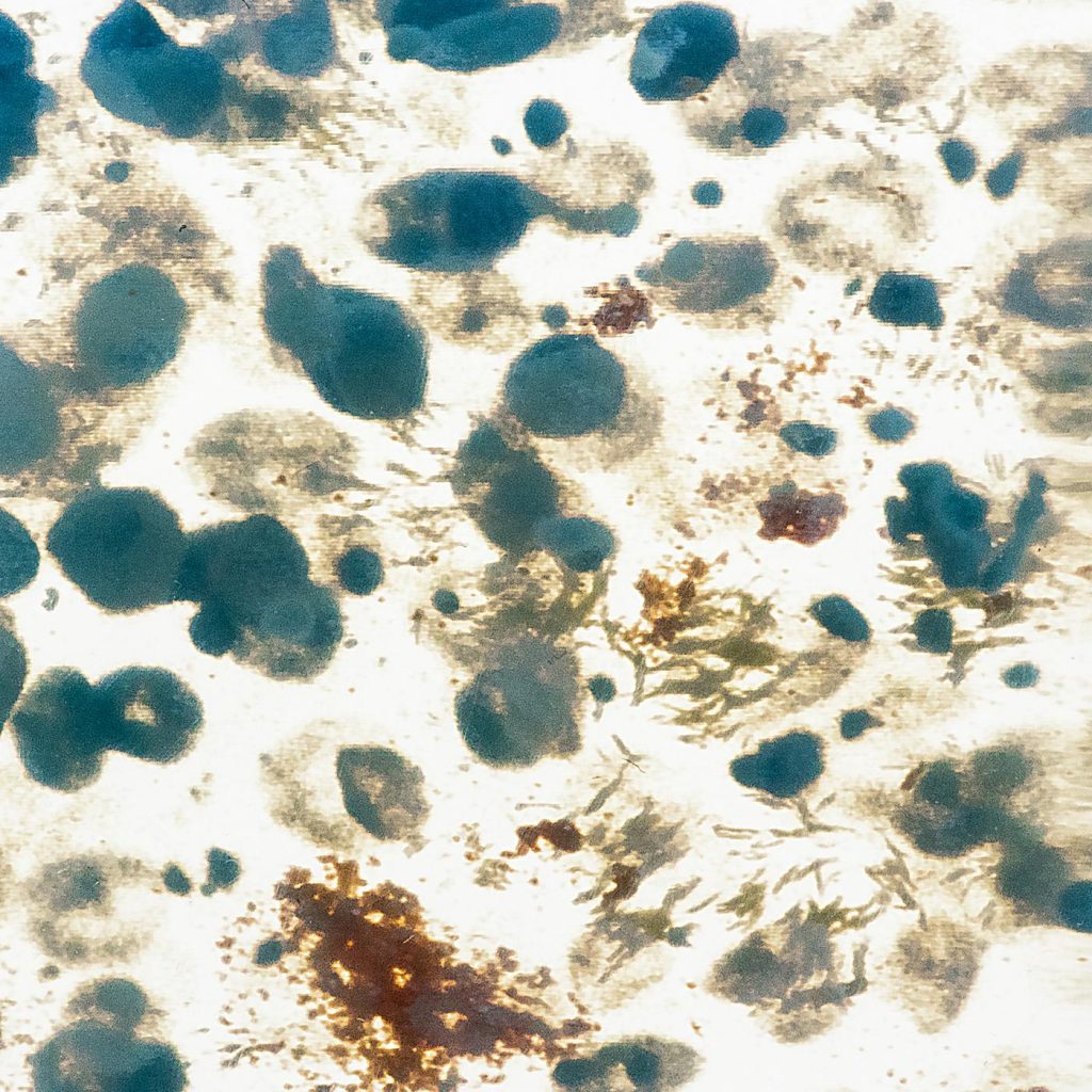
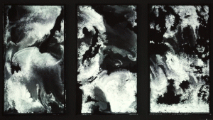
This art work, Frequencies (2017), caught my eye at first because I thought it was simply a model of different area’s geography because of the rocky surface, and liquid-like flow was the cloud movements in that area. I soon found that the rocky surfaces were randomly generated from different frequencies of Perlin Noise Algorithm. These generative 3D models have been created by Convivial Studio for Autodesk Pier 9. 

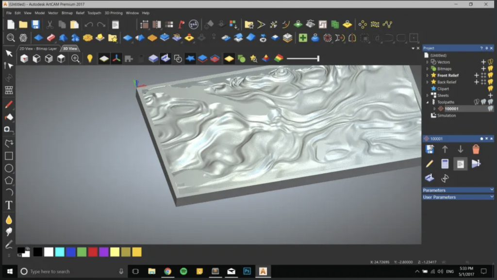
Look of a model generated from codes on ArtCam

For this shape and color study, Convivial Studio used artCam to generate GCodes of the frequencies of Perlin Noise Algorithm for the CNC (Computer Numerical Control) machines, which, then, generated infinite 3D models of the rocky surface. Then, these models were carved into condensed polyurethane foam board, added with the projection layer of different patterns changing over this board. This was a way of the team trying to challenge the viewer’s perception and get them engaged. This projection was created with several softwares such as openFramewors, ofxMtlMapping2D, ofxFlowTools and etc. 

It was very intriguing and eye-opening to see how lines of codes of noise frequencies could be translated into such beautiful art piece. 

Steven Fei – LookingOutwards – 03


Parametric design approach has always attracted me because of its elegant rationale and the infinite possibilities that we are able to create through controling different variables.

In the article from Prof Levin, what I think is the most meaningful work is the  “Blooming” Fibonacci Sculptures by John Edmark. Gaining inspirations from the phyllotaxis algorithm, the designer creates several 3D printing sculptures that give the illusion of contiunously blooming and extending while spinning. Through accurate parametric controlling, the artworks achieve strong fluidity in the transition between solid and void. Among those sculptures, the foliage-like piece and the opus with three mobius-strip-like pieces stacked on top of each other impressed me the most. As an architecture student, I once programed a similar “mobius” structure too through the use of Grasshopper and GhPython. Upon using the two plugins, I was able to control the number and size of the basic u-grids that made up of the circular section and the number and spacing of the v-grids that connects horizontally around the rims. Meanwhile, I was also able to decide where to start and end the shape. However, when I created such form, I only thought about of static shape while neglecting the dynamics when taking those parameters to flow overtime. I strongly admire the artist for his talent in thinking in a dynamic way to generate this amazing visual effect while rotating the object.

Moreover, in creating such moving and complex geometries, the artist managed to control those parameters so that the individual pieces can grow or morph while not interfering with each other overtime. Meanwhile, the individual artworks are stacked or combined in interesting ways to create new looks and more complex connections. Ultimately, through the use of parametric designs, the artist demonstrates the dynamic pattern that has seldom been created before and successfully creates a never-stopping illusion to the viewers.

Click here to visit the official website by the artist