Austin Garcia – Project 03 – Section C

I tried many different ways to create mountains and alter them somehow with the mouse. I first attempted to create a gradient on the shapes to give a sense of the sun shining on them from different angles. Eventually, I had to settle for drawing lines along the yellow mountains to give the sense of fog crawling across them. Click the canvas then drag your mouse along it.

sketch

/*		Austin Garcia
		Section C
		aegarcia@andrew.cmu.edu
		Project - 03
*/
var x1 = 0;
var y1 = 100;
var x2 = 80;
var y2 = 100;
var x3 = 40;
var y3;
var mountain1 = 5;
var c1;
var c2;
var diffx = 0;
var diffy = 0;
var targetX = 300;
var targetY = 300;
var x = 300;
var y = 300;
var r

function setup() {
    createCanvas(400, 100);
    background(220);
    y3 = random(40, 90);
    c1 = ("yellow");


  //  triangle (x1, y1, x2, y2, x3, y3)

}

function draw() {


    r = random(80);


    fill(c1);

    strokeWeight(4);
    stroke(225);
    diffx = mouseX / 2 - x;
    diffy = mouseY / 2 - y;
    x = x + 0.1 * diffx;
    y = y + 0.1 * diffy;
    line(x1, y1, x, y);
    line(x2, y2, x, y);


}
    function mousePressed() {

      push();
      translate(mountain1, 0);
      strokeWeight(1)
      triangle (x1, y1, x2, y2, x3, y3);
      pop();


    mountain1 = mountain1 + r;
    y3 = r;

    if (mountain1 > 400) {
      strokeWeight(0);
    }
}

Carly Sacco – Project-03- Dynamic Drawing


sketch

//Carly Sacco
//Section C
//csacco@andrew.cmu.edu
//Project 3

var x = 300;
var y = 400;
var dx = 1 ;
var dy = -1;

function setup() {
    createCanvas(640, 480);	
}

function draw() {
	background(95, mouseX * .7, 227);
	//fish head
	fill(50, 162, 168);
	noStroke();
	push();
	translate(width / 2, height / 2);
    rotate(PI / 4);
    rect(-50, -50, 300, 300, 30);
	pop();
	
	fill(184, 213, 214);
	noStroke();
	push();
	translate(width / 2, height / 2);
    rotate(PI / 4);
    rect(-25, -25, 250, 250, 30);
	pop();
	
	//fish eyes
	fill('white');
	ellipse(290, 315, 50, 65);
	ellipse(350, 315, 50, 65);
	
	fill('black');
	//letting the black of the eye move based on the mouse
	eyeY = constrain(mouseY, 310, 330);
	ellipse(290, eyeY, 35, 35);
	ellipse(350, eyeY, 35, 35);
	
	//fish  mouth
	fill(227, 64, 151);
	noStroke();
	push();
	translate(320, 410);
	rectMode(CENTER)
    rotate(mouseX / 150); //the mouth spins based on mouseX
    rect(0, 0, 100, 100, 30);
	pop();
	
	fill(120, 40, 82);
	noStroke();
	push();
	translate(width / 2, height / 2);
    rotate(PI / 4);
    rect(95, 95, 50, 50, 30);
	pop();	
	
	//fins
	fill(209, 197, 67);
	quad(460, 350, 510, 300, 510, 450, 460, 400);
	quad(200, 350, 150, 300, 150, 450, 200, 400);
	
	//bubbles
	var bub = random(25, 60);
	fill(237, 240, 255);
	ellipse(x, y, 50, 50);
	ellipse(x, y, bub, bub);
	ellipse(200, y, bub, bub);
	ellipse(mouseX * .5, mouseY * .5, bub, bub);
	ellipse(mouseX * .25, mouseY * .25, bub, bub);
	ellipse(mouseX * .75, mouseY * .75, bub, bub);
	ellipse(mouseX * .5, mouseY * .25, bub, bub);
	ellipse(500, y, bub, bub);
	ellipse(250, 500, bub, bub);
	x += dx;
	y += dy;

	//so that they bounce off the edges
	if (x > 640) {
		dx = -dx;
	}
	if (y < 0) {
		dy = -dy;
	}
	if (y > 480) {
		dy = -dy;
	}
	if (x < 0) {
		dx = -dx;
		dy = random(1,5);
	}	
}


I thought making a fish with aspects that moved based on the cursor would be a fun way of how humans normally try to get fish’s attention. I learned a lot about how certain things can be controlled and how with others it’s fun to let them just run.

Sarah Kang – Project 03- Dynamic Drawing

dydraw

//sarah kang
//section c
//sarahk1@andrew.cmu.edu
//project-03-dynamic-drawing

var angle = 0; //angle for rectangle rotation
var ogX = 0;
var ogY = 0;

function setup() {
    createCanvas(640, 480);
}

function draw() {
    background(0);
    strokeWeight(1.5);
    stroke(255, 255, 255);

    //top row small rectangles

    fill(mouseY, 102, mouseX);
    push();
    translate(70, 70);
    rotate(radians(angle * -1));
    rect(ogX, ogY, mouseX / 8, mouseY / 8);
    pop();
    push();
    translate(170, 70);
    rotate(radians(angle * -1));
    rect(ogX, ogY, mouseX / 8, mouseY / 8);
    pop();
    push();
    translate(270, 70);
    rotate(radians(angle * -1));
    rect(ogX, ogY, mouseX / 8, mouseY / 8);
    pop();
    push();
    translate(370, 70);
    rotate(radians(angle * -1));
    rect(ogX, ogY, mouseX / 8, mouseY / 8);
    pop();
    push();
    translate(470, 70);
    rotate(radians(angle * -1));
    rect(ogX, ogY, mouseX / 8, mouseY / 8);
    pop();
    push();
    translate(570, 70);
    rotate(radians(angle * -1));
    rect(ogX, ogY, mouseX / 8, mouseY / 8);
    pop();

    // middle medium rectangles, rotating in opposite direction

    fill(mouseX, 166, mouseY);
    push();
    translate(600, 230);
    rotate(radians(angle));
    rect(ogX, ogY, mouseX / 4, mouseY / 4);
    pop();
    push();
    translate(450, 230);
    rotate(radians(angle));
    rect(ogX, ogY, mouseX / 4, mouseY / 4);
    pop();
    push();
    translate(300, 230);
    rotate(radians(angle));
    rect(ogX, ogY, mouseX / 4, mouseY / 4);
    pop();
    push();
    translate(150, 230);
    rotate(radians(angle));
    rect(ogX, ogY, mouseX / 4, mouseY / 4);
    pop();
    push();
    translate(0, 230);
    rotate(radians(angle));
    rect(ogX, ogY, mouseX / 4, mouseY / 4);
    pop();

    //bottom big rectangles

    fill(mouseX, 255, mouseY);
    push();
    translate(100, 420);
    rotate(radians(angle * -1));
    rect(ogX, ogY, mouseX / 2, mouseY / 2);
    pop();
    push();
    translate(320, 420);
    rotate(radians(angle * -1));
    rect(ogX, ogY, mouseX / 2, mouseY / 2);
    pop();
    push();
    translate(540, 420);
    rotate(radians(angle * -1));
    rect(ogX, ogY, mouseX / 2, mouseY / 2);
    pop();

    angle = angle + 5; // rotation speed and direction

    //changing rotation speed, controlled by mouseX

    if(mouseX >= 320){
      angle = angle + 10;
    }
}

For this assignment, I was inspired by the parametric graphic references provided in the guidelines and wanted to emulate it through my drawing.

Aaron Lee-LookingOutwards-03

BUGA Fibre pavilion by  University of Stuttgart’s Institute for Computational Design and Construction (ICD) and the Institute for Building Structures and Structural Design (ITKE)

The BUGA Fibre Pavilion is a combined work of biomimicry research and computational design through the means of digital fabrication. The pavilion’s 60 woven structural are consisted of using synthetic glass and carbon fibers by robot arms. The resulting cylindrical modules got their inspiration from insect wings and exoskeletons. Both the innovative material and the genuine shape create structural rigidity and integrity that is much stronger than traditional means of steel construction while being much lighter for mobility after disassembly I am especially impressed by the appearance of the project which really features sci-fi aesthetic, we always imagine either in movie or show. Also, the fact that it leaves zero carbon foot print is inspirational.

Aaron Lee- Project-03- Dynamic Drawing

sketch

/*
Aaron Lee
//Section C
//sangwon2@andrew.cmu.edu
Project-03-Dynamic Drawing
*/

//variables

   var x = 0;
   var y = 100;

function setup() {
createCanvas(480, 640);
}


function draw() {
 
   background(0);
   stroke(0);
   fill(255, 204, 0);
   
   if (mouseY < (height / 2)) {
         fill(0);  
      }
   rect(10, 10, 30, 30);
   textSize(30);
   text('touch!', 40, 40);//if mouse is located on bottom portion of canvas, the text lights 

    fill(0);
   if (mouseY < (height / 2)) {
         fill(255, 204, 0);
      }
   rect(440, 600, 30, 30);
   textSize(30);
   text('touch!', 350, 630);//if mouse is located on top portion of canvas, the text lights

   push();

   translate(mouseX, mouseY);
   scale(mouseX/100, mouseY/100); 
   noFill();
   stroke(255);
   rotate(radians(x));
   rect(-50, -50, y, y);//scale of the rectangle changes following the movement of mouse

   x = x + mouseX/25;

   pop(); 

   stroke(255);

   //lines from top
   line(0, 0, mouseX, mouseY);
   line(40, 0, mouseX, mouseY);
   line(80, 0, mouseX, mouseY);
   line(120, 0, mouseX, mouseY);
   line(160, 0, mouseX, mouseY);
   line(200, 0, mouseX, mouseY);
   line(240, 0, mouseX, mouseY);
   line(280, 0, mouseX, mouseY);
   line(320, 0, mouseX, mouseY);
   line(360, 0, mouseX, mouseY);
   line(400, 0, mouseX, mouseY);
   line(440, 0, mouseX, mouseY);
   line(480, 0, mouseX, mouseY);
     //lines from right
   line(width, 40, mouseX, mouseY);
   line(width, 80, mouseX, mouseY);
   line(width, 120, mouseX, mouseY);
   line(width, 160, mouseX, mouseY);
   line(width, 200, mouseX, mouseY);
   line(width, 240, mouseX, mouseY);
   line(width, 280, mouseX, mouseY);
   line(width, 320, mouseX, mouseY);
   line(width, 360, mouseX, mouseY);
   line(width, 400, mouseX, mouseY);
   line(width, 440, mouseX, mouseY);
   line(width, 480, mouseX, mouseY);
   line(width, 520, mouseX, mouseY);
   line(width, 560, mouseX, mouseY);
   line(width, 600, mouseX, mouseY);
   line(width, 640, mouseX, mouseY);
        //lines from left
   line(0, 40, mouseX, mouseY);
   line(0, 80, mouseX, mouseY);
   line(0, 120, mouseX, mouseY);
   line(0, 160, mouseX, mouseY);
   line(0, 200, mouseX, mouseY);
   line(0, 240, mouseX, mouseY);
   line(0, 280, mouseX, mouseY);
   line(0, 320, mouseX, mouseY);
   line(0, 360, mouseX, mouseY);
   line(0, 400, mouseX, mouseY);
   line(0, 440, mouseX, mouseY);
   line(0, 480, mouseX, mouseY);
   line(0, 520, mouseX, mouseY);
   line(0, 560, mouseX, mouseY);
   line(0, 600, mouseX, mouseY);
   line(0, 640, mouseX, mouseY);
      //lines from bottom
   line(0, height, mouseX, mouseY);
   line(40, height, mouseX, mouseY);
   line(80, height, mouseX, mouseY);
   line(120, height, mouseX, mouseY);
   line(160, height, mouseX, mouseY);
   line(200, height, mouseX, mouseY);
   line(240, height, mouseX, mouseY);
   line(280, height, mouseX, mouseY);
   line(320, height, mouseX, mouseY);
   line(360, height, mouseX, mouseY);
   line(400, height, mouseX, mouseY);
   line(440, height, mouseX, mouseY);
   line(480, height, mouseX, mouseY);
}

I tried to make more user interactive animation with textual instruction.

Katrina Hu – Project 03 – Dynamic Drawing

sketch_project3

/*Katrina Hu
15104-C
kfh@andrew.cmu.edu
Project-03-Dynamic Drawing*/

var sunW = 50
var sunH = 50

function setup() {
    createCanvas(640, 480);
}

function draw() {
    //change background color
    background (191 - mouseY, 228 - mouseY, 255 - mouseY);
    noStroke();
    //change sun size
    if (mouseY < height / 2.5) {
        sunW = height / 3 - mouseY;
        sunH = height / 3 - mouseY;
    } 
    else {
        sunW = 10
        sunH = 10;
    }
    //draw sun
    //sun moves by mouseY
    fill (255, 247, 158);
    ellipse (300 - mouseY, 200 - mouseY, sunW, sunH);
    //draw houses
    //color of house lightens by mouseY/3
    //shape of house changes 
    fill(79 + mouseY / 3, 68 + mouseY / 3, 61 + mouseY / 3);
    rect(50, 380, 100 + mouseY / 25, 100);
    rect(200, 380, 100 + mouseY / 25, 100);
    rect(350, 380, 100 + mouseY / 25, 100);
    rect(500, 380, 100 + mouseY / 25, 100);
    triangle(100, 330, 30, 380, 170, 380);
    triangle(250, 330, 180, 380, 320, 380);
    triangle(400, 330, 330, 380, 470, 380);
    triangle(550, 330, 480, 380, 620, 380);

}

This project changes four different aspects of image elements – size, shape, position, and color. It was a fun project to do, as it was interesting to experiment with how mouse position would affect these elements.

Jai Sawkar – Looking Outwards – 03

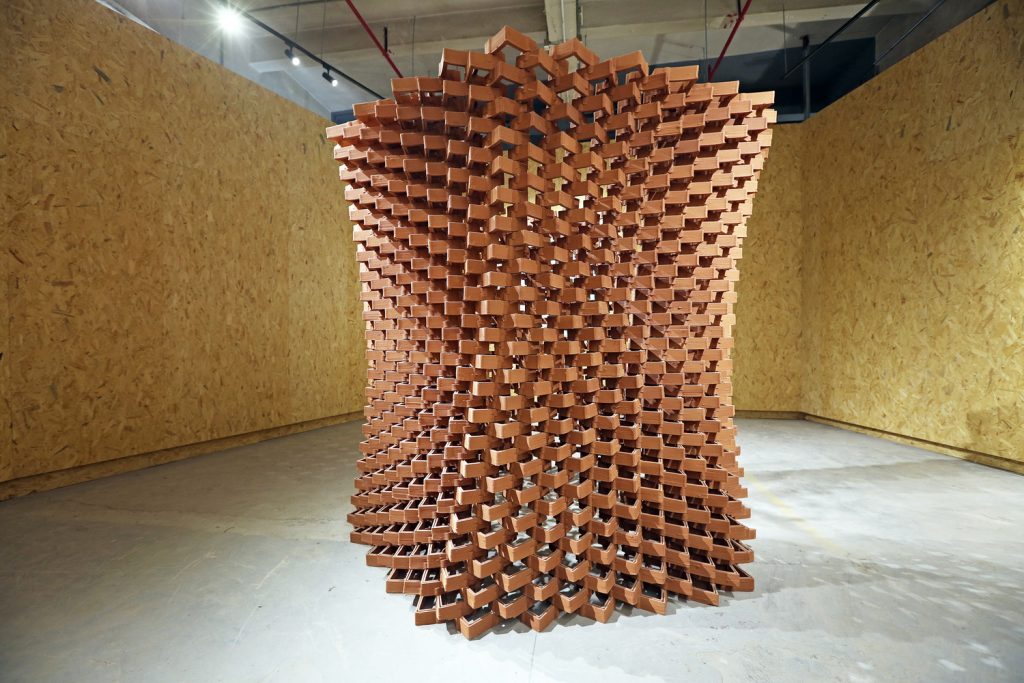
Experimental Pavilion of Ceramic Bricks in China by Robotic Fabrication LAB of The Faculty of Architecture of HKU

It is often argued that digital fabrication is the next step in fabrication, both at a large scale and small scale. Technology companies use laser cutters, 3D printers, and CNC routers in both their iterative & final products and architecture & design are following as well. With digital fabrication, components can not only be more precise, but more dynamic as well. It is reasons like this that organizations, like the Robotic Fabrication LAB of the Faculty of Architecture of HKU, are beginning to change the status-quo of components dating back centuries.

When bricks used in structures were first mass-produced, they were made in small rectangles, allowing both consistency and allowing it to be held in a single hand, easily, by builders. Now with advancements in digital fabrication, designers, like the one noted above, can begin to change our perception of bricks; in this case, both the shape and the material are unlike what the common person is used to.

This is incredibly interesting and intriguing to me, as I, and many others, believe that this type of technology will advance tremendously in the next decades. With these advancements, I truly cannot wait to see what new structures and forms can be created with a plethora more of opportunity.

Article

Katrina Hu – Looking Outwards – 03

Voxel-Printing of the Human Brain

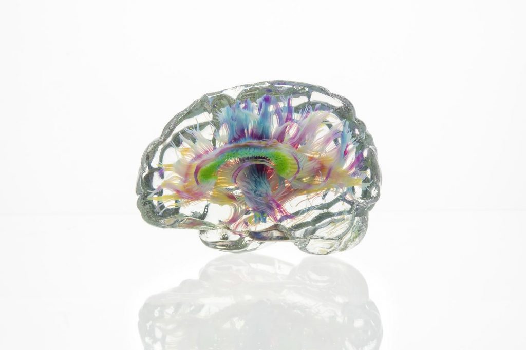
Data physicalization of the human brain, made by the Mediated Matter Group

The Mediated Matter Group at MIT uses a multimaterial voxel-printing method. This enables the physical visualization of data sets. These data sets are visualized on a screen, and then converted into physical 3-D objects. One of the objects that stood out to me was the physicalization of the human brain. The viewer is able to see various brain structures, including bundles of axons that connect different parts of the brain.

I admire this work because it allows people to actually visualize structures that may otherwise be hard to see. It is very effective, as physical manifestations of data sets can improve spatial perception skills. It also makes the presentation of new information more intuitive for students. It allows much more interaction than 2-D information displays.

To generate this work, the group converts data sets into dithered material deposition descriptions. The data sets then can be visualized on screen and can later be converted into physical objects. 

Carly Sacco – Looking Outwards – 03

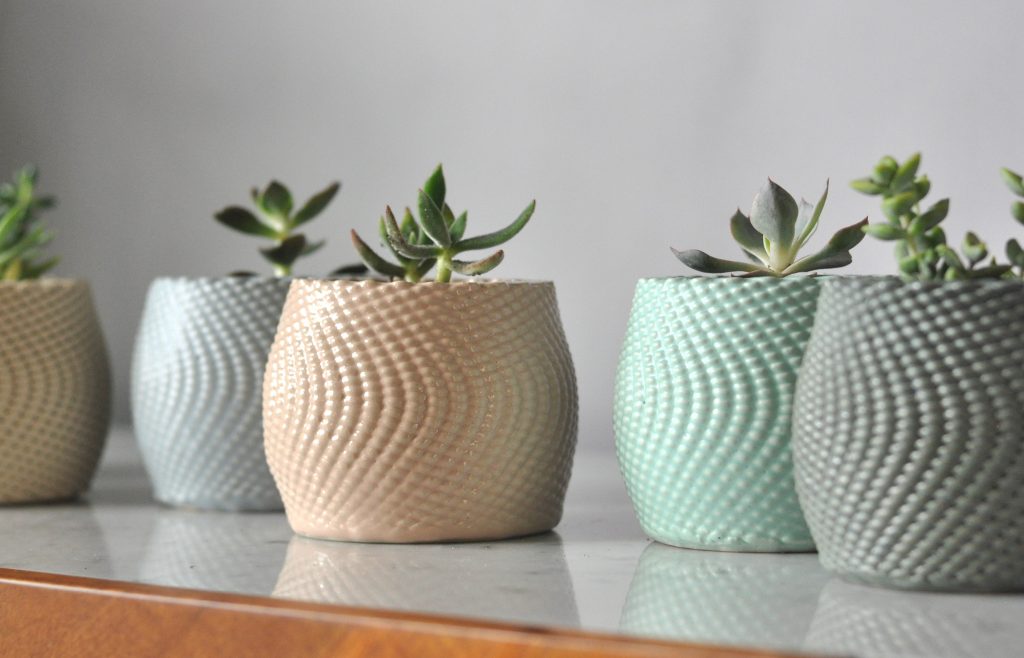
Coded Clay is a project and business where 3D parametric fabrication creates pots and vases for people to use in their homes. This project is particularly interesting because code is used to alter every aspect of the 3D printing process to create unique vases. The 3D printer is also custom built to be able to print clay after using parametric coding in grasshopper.

The 3D printer prints clay in an arrangement coded and designed parametrically.

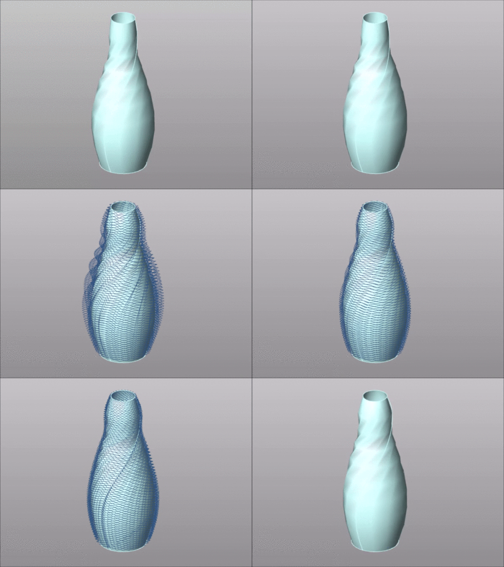
The process taken to create the pots starts by a sketch idea of a form/shape. Then by the use of parametric coding in grasshopper, the forms are digitally modified until the desired aspects of the pot are met. Lastly, the pots are 3D printed, fired twice, and hand glazed. Brian Peter is the creator of these and he if interested in both computational architecture as well as pottery. He went to undergrad for Studio Art and completed a ceramic residency – where the 3D printed clay idea started.

The pots are coded parametrically before the printing process begins.

Austin Garcia – Looking Outwards – 03 – Section C

“Mass Regimes” by – Epiphyte Lab

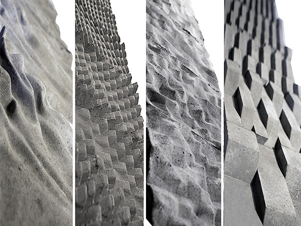
The Epiphyte Lab’s study “Mass Regimes” is an exploration in implemented parametric modeling and CNC work. By programming a CNC machine to ‘print’ concrete in complex forms, they are able to experiment with the thermal properties of the concrete. These different computational forms all allow for differing heat transfer through the material. By studying the thermodynamic performance of different complex forms, the Epiphyte Lab is able to test new and unique thermal strategies for passive heating and cooling of buildings.

The Process for creating these surfaces most likely involved crafting parametric functions which created 3d digital models. These models were then read and ‘printed’ by a CNC machine capable of printing with Concrete. The specific parameters for these forms had to do with varying size, geometric complexity, and density of forms in order to experiment with the thermal properties of the concrete.