Carley Johnson Project 3

sketch

/*Carley Johnson
cbjohnso@andrew.cmu.edu
Section E
Project 3
*/


var x = 80;
var y = 30;
var w = 12;
var h = 12;
var starR = 252
var starG = 234
var starB = 109
var moonR = 236
var moonG = 236
var moonB = 236
var moonR2 = 109
var moonG2 = 110
var moonB2 = 106
var bckgrndR = 37
var bckgrndG = 21
var bckgrndB = 66

function setup() {
    createCanvas(640, 480);
    frameRate(10);
}

function draw() {
  background(bckgrndR, bckgrndG, bckgrndB)
  
    fill(252, 234, 109)
    noStroke()
    ellipse(mouseX, mouseY, 10, 10) //constellation
  
    fill(moonR, moonG, moonB)
    ellipse(100, 100, 80, 80) //moon
  
    fill(moonR2, moonG2, moonB2)
    ellipse(115, 100, 50, 70) //moon dark side

    stroke(252, 234, 109)
    line(mouseX, mouseY, pmouseX, pmouseY);
    print(pmouseX + ' -> ' + mouseX); //constellation maker

    noStroke()
    fill(starR, starG, starB) //Begin stars for night sky
    ellipse(x, y, w, h);

    ellipse(x + 80, y + 310, w, h); //star 1

    ellipse(30, y + 400, w, h - 2); //star 2

    ellipse(x + 10, y + 190, w, h); //star 3

    ellipse(x + 200, y +30, w, h); //star 4

    ellipse(x + 250, y + 90, w - 2, h - 2); //star 5

    ellipse(x + 270, y + 380, w, h); //star 6

    ellipse(x + 180, y + 30, w - 2, h -2); //star 7

    ellipse(x + 400, y + 75, w - 2, h - 2); //star 8

    ellipse(x + 420, y + 300, w, h); //star 9

    ellipse(x + 370, y + 130, w - 2, h - 2); //star 10

    ellipse(x + 500, y + 30, w, h); //star 11

    ellipse(x + 20, y + 285, w, h); //star 12

    ellipse(x + 120, y + 120, w - 2, h -2); //star 13

    ellipse(x + 145, y + 200, w, h); //star 14

    ellipse(x + 500, y + 300, w, h); //star 15

    ellipse(x + 200, y + 205, w - 2, h); //star 16

}

function mouseMoved() {
  starB = starB + 3;
  if (starB > 250) {
    starB = 109;
  }
}

function mousePressed() {
  if ( moonR === 236) {
    moonR = 252;
  } else {
    moonR = 236;
  }

  if ( moonG === 236) {
    moonG = 234;
  } else {
    moonG = 236;
  }

  if ( moonB === 236) {
    moonB = 109;
  } else {
    moonB = 236;
  }

  if ( moonR2 === 109) {
    moonR2 = 252;
  } else {
    moonR2 = 109;
  }

  if ( moonG2 === 110) {
    moonG2 = 234;
  } else {
    moonG2 = 110;
  }

  if ( moonB2 === 106) {
    moonB2 = 109;
  } else {
    moonB2 = 106;
  }

  if ( bckgrndR === 37) {
    bckgrndR = 108;
  } else {
    bckgrndR = 37;
  }

   if ( bckgrndG === 21) {
    bckgrndG = 214;
  } else {
    bckgrndG = 21;
  }

   if ( bckgrndB === 66) {
    bckgrndB = 251;
  } else {
    bckgrndB = 66;
  }

  if ( starR === 252) {
    starR = bckgrndR;
  } else {
    starR = 252;
  }

  if ( starG === 234) {
    starG = bckgrndG;
  } else {
    starG = 234;
  }

  if ( starB === 109) {
    starB = bckgrndB;
  } else {
    starB = 109;
  }

}


This was fun! Move your mouse to make the stars twinkle and create a shooting star, and if the night isn’t your thing, click to turn the scene to daytime! It was tough juggling a lot of elements and variables, but I think this is quaint and I feel like I learned a lot twiddling with the different mouse functions.

Looking Outwards-03 Computational Fabrication-Veronica Wang

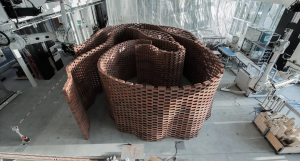
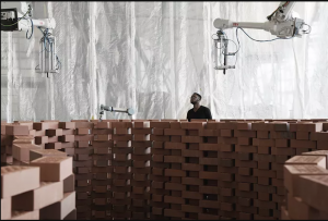
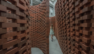
The Brick Labyrinth is a project done at ETH Zurich’s Architectural department using programming in the design process and robotics fabrication. On their website it is described that「 The Brick Labyrinth is re-visiting one of the most archaic building techniques, dry-stacked brick walls, in a completely new setting…the Master of Advanced Studies used the multi-robotic gantry system in the Robotic Fabrication Laboratory to build a full-scale architectural installation of a brick labyrinth. Students used computational tools not only to iterate through designs but also to check the stability and feasibility of the produced structures and to generate the sequence and commands to control the multi-robotic fabrication of the final structure. 」

Top View of Final Installation
Fabrication in Process
Experiential Capture

I took a robotics centered architectural design studio last semester and we took a lot of inspiration from the ETH program. I am interested in especially how robotics fabrication can aid construction processes and its ability to accurately execute complex designs within a shorter amount of time because of the streamlined process.

Alice Fang – Looking Outwards – 03

Vespers, Series 2, Mask 5. Bottom View. 2016. Photo: Yoram Reshef
Vespers, Series 2, Mask 5. Close-up view.

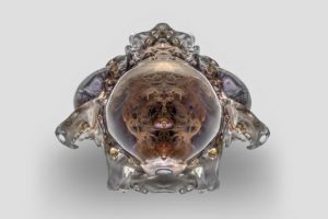
Vespers: Series II is the second of a three-part series produced by the Mediated Matter group at MIT’s Media Lab that explores how designing masks relates to “design (with) life.” This part examines the transition between life and death, and marks a progression from the first part of the project- looking at death masks as a cultural object- to the third part- using death masks as a “functional biological interface.” A theme that surrounds this second part is the idea of metamorphosis, moving from a symbol of life and death to the concept of wearable skins and interfaces.

The structures of these masks are designed to match actual biological structures observed in nature, and spatial mapping algorithms are used to translate color and geometry from the first part of the series into internal structures in this second part. Each mask also has a unique dataset that informs the distribution of the materials in its print.

I admire how a concept so abstract as this can create objects that are so detailed and delicate-looking from computer generation. It amazes me that these were 3-D printed, but I suppose 3-D printing has evolved so much in the past few years, where glass and porcelain can be printed now too. It’s also very interesting conceptually, to consider how the idea of life and death can transform into a technological and biological tool for skins and surfaces.

Jamie Dorst Looking Outward 03

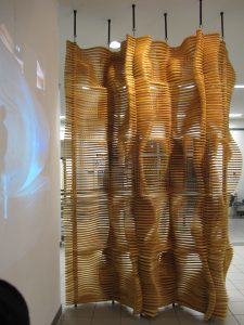
For this week’s Looking Outward post, I decided to write about a project called Zero/Fold Screen made in 2010 by a design studio called Matsys.

Zero/Fold Screen–a light filtering undulating wooden screen.
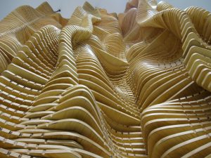
A different view of Zero/Fold Screen, showing its interesting dimensions.

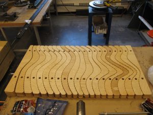
This screen is made of wood, and is light-filtering. It was placed in a gallery in Canada. I was inspired by this project because they used digital fabrication to help reduce their material waste. A lot of times when building these types of projects, the size of the material is considered at the end, resulting in a lot of wasted material. This project generated components based on the size of their materials, reducing waste. It wasn’t clear what software they used to create the components, but they were cut on a CNC.

Some of the components of Zero/Fold Screen, demonstrating how they were cut so as to fit the original piece of wood.

I think it’s really cool that they’re using this technology to create something that is practical for use and for sustainability. It inspires me to use technology to create things that are beneficial for the world. It shows me that it is possible to be mindful of the implications of what I am creating, so that I can make the best thing possible.

Vicky Zhou – Looking Outwards – 03

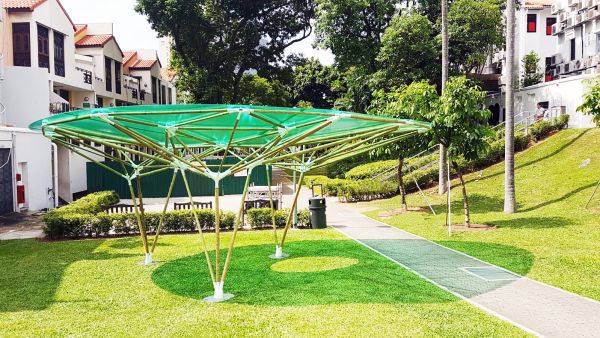
“Sombra Verde”

“Sombra Verde” is a bamboo pavilion constructed by AIRLAB and Singapore University of Technology and Design utilizing raw bamboo poles, 3D printed connectors, and a transparent polycarbonate roof. Unlike traditional building methods, which utilize natural materials haphazardly and through guess and check estimation to a certain extent, the researchers, designers, and builders for Sombre Verde constructed this canopy with the optimization of each bamboo pole’s position. To do so, they measured and digitized the thickness, height, and bend of each bamboo pole, processed that in their algorithmic machine, which then calculated the optimal capacity and positioning of each pole. In addition, this data was used to design and fabricate the connecting PLA (inexpensive, plant based plastic) that would hold these bamboo poles together. In juxtaposition with the rigid computation of optimal bamboo positioning, the designer’s personal sensibilities shine through with the choice of a bright green, roof, which seem to mimic a large leaf.

I appreciate this architectural piece because of how it incorporates an obviously man-made shelter into nature (bright plastic green roof), without stripping the project of certain natural components (raw bamboo poles) whilst using technology to optimize it’s strength and infrastructure so that it can stand the test of time and nature, rather than become obsolete and broken in a couple years time.

PLA connectors
aerial view

Jenni Lee – Looking Outwards – 03

Demonstrative video of the 3D Printed Ceramics

Link

Engineer Zack Eckel, based in Malibu, California, creates 3D-printed free-form, strong, and temperature resilient ceramics. These ceramics can withstand pressure and heat without breaking, warping, or cracking. By 3D printing these essentially invincible ceramics, Eckel addresses the design problems of both ceramics and of regular 3D printing. Ceramics, such as ceramic plates or mugs, are typically made of clay, easily breakable, despite their strong presence in American households. By designing these flawless, strong, 3D-printed ceramics, Eckel re-envisions and redefines the boundaries of ceramics. In addition, Eckel address the design problem of 3D printing products, as the material that typical 3D printers utilize are not heat resistant or particularly pressure resistant. As a result, Eckel uses stronger, revolutionary 3D-printing materials in order to address this. I found Eckel’s work to be not only aesthetically captivating, but also highly revolutionary in terms of human factors and ergonomics.

Emily Zhou – Looking Outwards – 03

FLUIDIC – Sculpture in Motion is an art installation produced design studio WHITEvoid for the Hyundai Advanced Design Center.

Single phase of FLUIDIC – Sculpture in Motion

The project is intended to embody Hyundai’s adaptive and evolving design language; as tiny spheres act as randomly distributed molecules that aggregate and illuminate based on viewer interaction. I am inspired by the breadth of visual experience that is created by such a large collective small objects.

The work uses a water pond, 12,000 illuminated spheres, and 8 high-speed laser projectors to create a physical point cloud. A computer algorithm randomizes the arrangement of the cloud particles based on the positions and projection angles of the projectors. The program also analyzes the positions of the viewers by calculating their posture and gestures using 3D camera tracking systems. This data is used to determine the cloud’s dynamic motion.


[above]
Video documentation of the FLUIDIC – Sculpture in Motion installation; shows viewer interaction and reaction.

The artwork is an innovative example of parametric 3D fabrication that I particularly admire for its ability to account for viewer interaction in its algorithm.

Connor McGaffin – Looking Outwards – 03

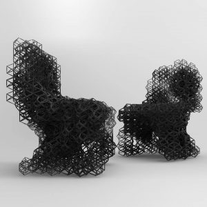
“Deoptimized Chair” – Daniel Wildrig (2013)                                                                                    an  exploration of generative form in furniture (source)

Daniel Wildrig is a sculptor as well as a fashion and furniture designer whose work explores generative form at the intersection of a geometric and organic qualities. Formerly working alongside Zaha Hadid, Wildrig was heavily involved in the process of creating some of the studio’s most iconic buildings.

Wildrig’s sensibilities are relatively aligned with the work while at Hadid, however on a much smaller scale. The buildings designed at Wildrig’s former studio also shares aesthetic similarities with the natural world.

I am drawn to this particular project because of its seemingly complex solution to the relatively simple design problem of creating an object for resting. I also am engaged by the further juxtaposition of such sharp forms that work to create an artifact for comfort.

I would suppose that the algorithms that led to this final product consist of some sort of base “unit”, likely the dynamic hexagonal shape seen on the outskirts of the chair. There is likely a random generation of these units with a higher assigned density at the structural core of the chair.

(source)

Min Jun Kim- Looking Outwards 3

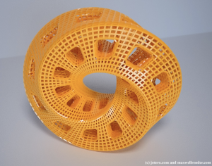
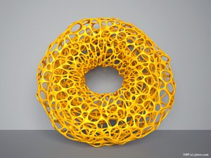
Artwork by Torolf Sauermann.

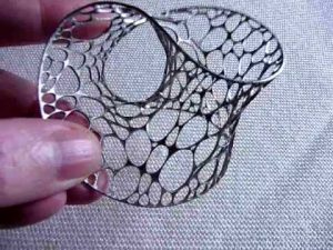
This week’s topic is about computational fabrication. While doing some research, I came across an artist by the name of Torolf Sauermann. He creates a lot of unique sculptures that have been 3D printed as the ones shown above. He creates fascinatingly impossible figures that probably couldn’t be constructed by a human alone. What I admire the most about his artwork is that it endlessly pushes the boundaries of the 3D world. The artwork presented above has the characteristics of a Möbius strip which is a ring that only has one side. I admire the fact at how intricate it is and how insanely difficult it would be to create without the usage of a 3d printer.
As for how it was generated, I think that it was definitely modeled by a 3d rendering software. I assume that he had a simpler version of the model, like a skeleton or some lines, that were filled in and made more intricate over time through the usage of algorithms. I think the artist’s genius to create such forms in his mind simply manifested into material form.

Below are some of his other artworks:

Another artwork by sauermann

sauermann.

Some links to the sources of the art found online:
http://www.evolution-of-genius.de/gallery/default1.htm
https://imaginary.org/users/torolf-sauermann
https://viz.arch.tamu.edu/

Min Jun Kim -Project 3 Dynamic Drawing Section B

sketch

/*
Min Jun Kim
minjunki@andrew.cmu.edu
15104-B
Project 3
*/

function setup() {
    createCanvas(640, 480);
}

function draw() {

	//set up and first quad 
	strokeWeight(3);
	push();
	background(mouseX);
	translate(width/2,height/2);
	rotate(mouseX/-100);
	drawQuad();
	pop();

	//the oval representing the eye
	push();
	fill(mouseX);
	translate(width/2,height/2)
	ellipse(0,0,mouseX*1.9,mouseX*1.3)
	pop();

	//red circle in middle
	push();
	translate(width/2,height/2);
	fill(mouseX*255/640,10,10);
	ellipse(0,0,mouseX,mouseX);
	pop();

	//a ring around the spinning reverse quads
	push();
	translate(width/2,height/2);
	fill(mouseX*255/640,10,10)
	ellipse(0,0,mouseX/1.3,mouseX/1.3);
	pop();

	//quad 2	
	translate(width/2,height/2);
	push();
	fill(0);
	rotate(mouseX/-300);
	quad(-mouseX/3,0,0,mouseX/3,mouseX/3,0,0,-mouseX/3)
	pop();

	//quad 3
	push();
	fill(mouseX*255/640,10,10)
	rotate(mouseX/-400);
	quad(-mouseX/4,0,0,mouseX/4,mouseX/4,0,0,-mouseX/4)
	pop();

	//quad 4
	push();
	fill(0);
	rotate(mouseX/-500);
	quad(-mouseX/5,0,0,mouseX/5,mouseX/5,0,0,-mouseX/5)
	pop();

	//quad 5
	push();
	fill(mouseX*255/640,10,10)
	rotate(mouseX/-600);
	quad(-mouseX/6,0,0,mouseX/6,mouseX/6,0,0,-mouseX/6);
	pop();

	//quad 6
	push();
	fill(0);
	rotate(mouseX/-700);
	quad(-mouseX/7,0,0,mouseX/7,mouseX/7,0,0,-mouseX/7);
	pop();

	//spinning rect 1
	push();
	fill(0);
	rotate(mouseX/30-0.4);
	rect(mouseX/4,mouseX/4,mouseX/20,mouseX/20);
	pop();

	//spinning rect 2
	push();
	fill(0);
	rotate(mouseX/30+1.6);
	rect(mouseX/4,mouseX/4,mouseX/20,mouseX/20)
	pop();

	//spinning rect 3
	push();
	fill(0);
	rotate(mouseX/30-2.5);
	rect(mouseX/4,mouseX/4,mouseX/20,mouseX/20)
	pop();

	//upper black cover
	push();
	fill(1);
	noStroke();
	rect(-400,-100+mouseX*2,1000,1000);
	pop();

	//lower black cover
	push();
	noStroke();
	fill(1);
	rect(-400,-200-mouseX*2,800,300)
	pop();


}

//function that draws quads
function drawQuad() {
	quad(-mouseX/2,0,0,mouseX/2,mouseX/2,0,0,-mouseX/2);
	
}


The project is based on dynamically drawing when mouse is moved across the horizontal axis (mouseX).
The process was rather simple and started with me messing around with the rotate function. I was rotating a quad and I thought that overlaying the quad with multiple quads would look pretty cool. I initially tried to call the drawQuad function that I made to create multiple quads, but I quickly learned that doing so will make identical quads and so I had to manually create multiple quads in the middle by differing the speed at which it grows. The manual process however became a lot easier once I learned about the Push() and Pop() on this week’s readings. After creating multiple rotating quads in the middle I realized the it reminded me of the sharingan from Naruto and went along with it to create something that somewhat resembles it. I ended up manipulating size, position, angle, color and speed.
All in all, I had a lot of fun figuring things out for this project.