Xiaoyu Kang – Looking Outwards – 03

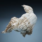
The Suture Chair is developed by Andrew Kudless in 2005. The chair itself is an extension of his “Honeycomb Morphologies/Manifold research project” that a double layered honeycomb system is used in designing the chair.


The honeycomb structure allows the chair to be both flexible and stable in shape, the chair itself however is able to rock in different directions and seating configurations. The exterior shape of the chair is designed based on the idea of suture curve, which is the same curve that is used to put balls such as the tennis ball together. The rings that made up the structure of the chair is known to have the minimal surface known as a Enneper surface spans, which also allows the chair supporting structure to be the thickest at the edge and the thinest at the center. To balance out the structural strength, a higher density of honeycomb members are put in the center of the chair, which also turns out to require the least structural depth in each of the cell units.

Xu Xu – Looking Outwards – 03

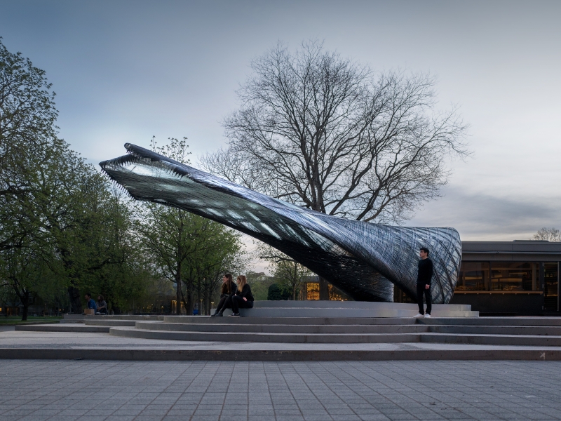
The project that I decided to choose is the ICD/ITKE Research Pavilion 2016-17: Interactive Panorama by Heiko Stachel. This research pavilion investigates building scale fabrication of glass and carbon-fibre reinforced composites. I was attracted to it due to its unique form, and I admire the beautiful cantilever structure that incorporates a sort of weaving pattern. Due to the fibre composites’ lightweight and long-span characteristics, the project was carried out using different methods: a combination of unmanned aerial vehicles (UAE), which has low payload but long-range, and industrial robots, which is precise, strong but has limited reach. According to the research institute, this design was inspired by “two species of leaf miner moths, the Lyonetia clerkella and the Leucoptera erythrinella, whose larvae spin silk “hammocks” stretching between connection points on a bent leaf”. Certain concepts were abstracted from the biological models such as the combination of bending structures, fibre orientations and hierarchy, and three-dimensional geometries to create the new, innovative form.

The algorithm methods weren’t listed in the research institute’s website, but I assume that the fabrication of this structure is similar to 3d printing, but on a much larger scale. The algorithm somehow transforms the digital model (perhaps done by Rhinoceros), and uses robots to print out the structure layer by layer.

Ankitha Vasudev – Project 03- Dynamic Drawing


For this project I wanted to experiment with rotation and changes in color. I tried to create contrasting changes such as the sun color changing as its size decreases and the buildings rising and becoming brighter as the sky gets darker. The most challenging part was getting the rotation of the sun rays.

sketch

// Ankitha Vasudev
// Section B, 10:30 - 11:50
// ankithav@andrew.cmu.edu
// Assignment-03-b

function setup() {
    createCanvas(480, 640);
}

function draw() {
	// Changes background color based on mouse position 
	background(0, 200 - mouseX, 500 - mouseY);
	noStroke();

    //Local variables
    var x = 700; //triangle x coordinate
    var y = 700; //triangle y coordinate 
    var circleW = 30; //sun width
    var circleH = 30; //sun height
    var bwidth = 50; //building width

    //rotating sun rays (triangles)
	push();
	translate(mouseX, mouseY);
	fill(255, 225, 0);
	rotate(mouseY);
	triangle(0, 0, -x/2, y, -x, y+200);
	triangle(0, 0, x/2, -y, x, -y-200);
	triangle(0, 0, x+50, y, y, x+50);
	triangle(0, 0, -x-50, -y, -y, -x-50);
    pop();

    //sun - circle changes size based on mouse position 
    if (mouseX < width/2) {
    circleW = width/2 - mouseX;
    circleH = width/2 - mouseX;
    } else { 
    circleH = 5
    circleW = 5;
    }
    
    //changes sun color and size
    fill(255, 225, mouseX);
    ellipse(mouseX, mouseY, circleW, circleH);

    //building heights based on mouse position 
    fill(mouseX);
    rect(200, 530, bwidth+10, (-mouseY/ 5));
    fill(220);
    rect(160, 570, bwidth-10, (-mouseY / 5));
    fill(150);
    rect(70, 600, bwidth, (-mouseY/5));
    fill(mouseX);
    rect(380, 620, bwidth, (-mouseY/5));
    fill(180);
    rect(355, 550, bwidth/2, (-mouseY/5));
    fill(mouseX);
    rect(20, 660, bwidth/3, (-mouseY/5));

    //green ground - stationary
    fill(0, 220, 70);
    ellipse(width/2, 870, 700, 700);
}

Siwei Xie-Looking Outwards-04

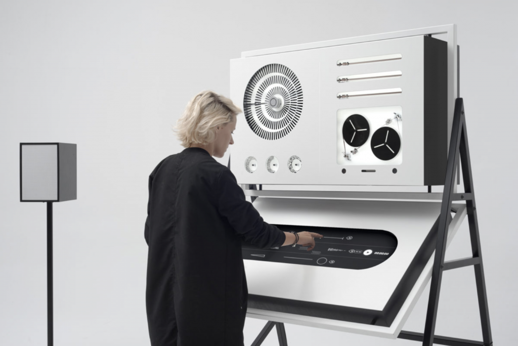
Using “Apparatum” created by panGenerator in 2018.

Apparatum is a custom made apparatus with digital interface that emits purely analogue sound. I admire the project because it takes inspirations from earlier studios and musician, then gives it a modern twist. The physical form is inspired by Polish Radio Experimental Studio, which uses magnetic tape as primary medium. Musically, it is inspired by Boguslaw Schaeffer, who conceived his own visual language of symbols that conveyed the cues for sound engineers. 

The creator, panGenerator, utilizes electron (node.js) and c running on teensy 3.2 to generate  interface and micro-controller elements. Creator’s artistic sensibility manifests by borrowing from Oskar Hansen’s “Black Room.” The original design was generated more than 100 years ago, yet panGenerator is able to add touch screen and modern studio elements to create a chic apparatus. The black and white combination would easily catch consumers and artists’ eyes today.

Link to original source is here.

Siwei Xie-Project 03-Dynamic Drawing

sketch

//Siwei Xie
//Section B
//sxie1@andrew.cmu.edu
//Project-03

var angle = 0;

function setup() {
    createCanvas(640, 480);
}
 
function draw() {
	// change background color when mouse moves
    background(205, mouseX/3, mouseY/6);
    noStroke();

    // 3 black objects in background follow mouse's movements,
    // creating a dynamic triangle with changing colors
    fill("black");
    triangle(0, 0, mouseX, mouseY, 0, 480);
    triangle(mouseX, mouseY, 640, 0, 640, 480);
    rect(0,0,640,mouseY);

    // enlarge mouth when mouse moves right
    // mouth position follows mouse
    fill("pink");
    circle(mouseX,mouseY+180,mouseX/2);

    // left rotating eye
    // eye position follows mouse
    fill("white");
    push();
    translate(mouseX-80, mouseY);
    rotate(radians(angle));
    rectMode(CENTER);
    rect(0, 0 , 60, 60);
    pop();
    angle = angle + 3;

    // right rotating eye
    push();
    translate(mouseX+80, mouseY);
    rotate(radians(angle));
    rectMode(CENTER);
    rect(0, 0 , 60, 60);
    pop();
    angle = angle + 3;

    // text enlarges when mouse moves right,
    // and follows mouse's verticle position
    textSize(mouseX/8);
    textFont("old english");
    text("Monster is roaring",0,mouseY/2);
 

}

I drew a monster which follows the mouse’s movements. The monster would roar if mouse moves right, and would “stay calm” if mouse moves left.

Sewon Park – PO – 03

sketch

//Sewon Park
//sewonp@andrew.cmu.edu
//Section B
//Project-03


var angle = 10 // used for rotation of squares later
function setup () {
createCanvas(640,480)

}

function draw () {
background(dist(320,240,mouseX,mouseY)); //background color dependent on mouse location from center


//Ellipse that moves with center at mouse location (Main Ellipse)
fill(mouseX,0,mouseY); // color dependent on mouse movement
stroke(0);
ellipse(mouseX,mouseY,mouseX/2,mouseY/2) // position and size dependent on mouse movement

 //Ellipse2 moves diagnally from main ellipse with mouse movement away from center. 
var x = width - mouseX
var y = height - mouseY 
fill(mouseX,0,mouseY) // color dependent on mouse movement
stroke(0);
ellipse(x,y,mouseX/2,mouseY/2)
x = x - 3
y = y - 3  

//Ellipse3 moves vertically from main ellipse from mouse movement away from center.
var x2 = 0 + mouseX
var y2 = height - mouseY
fill(0,mouseX,0) // color dependent on mouse movement
stroke(0);
ellipse(x2,y2,mouseX/2,mouseY/2)
x2 = x2 - 3
y2 = y2 + 3

//Ellipse4 moves horizontally from main ellipse from mouse movement away from center.
var x3 = width - mouseX
var y3 = 0 + mouseY
fill(0,mouseX,0) // color dependent on mouse movement
stroke(0);
ellipse(x3,y3,mouseX/2,mouseY/2)
x3 = x3 - 3
y3 = y3 + 3

//Square1 spins with its corner respect to main ellipse's center
fill(0,mouseY,mouseX); //color dependent on mouse movement
stroke(0);
push();
translate(mouseX, mouseY);
rotate(angle);
rectMode(CORNER); 
rect(0, 0, 50, 50);
pop();
angle = (angle+dist(320,240,mouseX,mouseY))*0.5; // rotation speed dependent on mouse movement

//Square2 spins with its corner respect to ellipse 2's center
fill(0,mouseY,mouseX);  //color dependent on mouse movement
stroke(0);
push();
translate(x, y);
rotate(angle);
rectMode(CORNER); 
rect(0, 0, 50, 50);
pop();
angle = (angle+dist(320,240,mouseX,mouseY))*0.5; // rotation speed dependent on mouse movement

//Square3 spins with its corner respect to ellipse 3's center
fill(0,mouseY,mouseX);  //color dependent on mouse movement
stroke(0);
push();
translate(x2, y2);
rotate(angle);
rectMode(CORNER); 
rect(0, 0, 50, 50);
pop();
angle = (angle+dist(320,240,mouseX,mouseY))*0.5; // rotation speed dependent on mouse movement

//Square4 spins with its corner respect to ellipse 4's center
fill(0,mouseY,mouseX);  //color dependent on mouse movement
stroke(0);
push();
translate(x3, y3);
rotate(angle);
rectMode(CORNER); 
rect(0, 0, 50, 50);
pop();
angle = (angle+dist(320,240,mouseX,mouseY))*0.5; // rotation speed dependent on mouse movement

}

This project was probably the toughest yet as coordinating movements to your mouse movements is no easy task. I tried to incorporate two different types of movements through altering position and rotation in respect to change in cursor position.

Chelsea Fan-Project-03-Dynamic Drawing

DynamicDrawing

/* Chelsea Fan
Section 1B
chelseaf@andrew.cmu.edu
Project-03
*/

//Changes in size, position, shape, and distance
function setup() {
    createCanvas(640, 480);
    noStroke();
}

function draw() {
    background(173, 216, 230);
    fill(255,255,0);
    //MouseX can move from 50 to 450
    var mouse = max(min(mouseX, 450), 50);
    var size = mouse * 400.0 / 640.0;
//Rabbit 1
    //Body
    fill(250, 250 , 250);
    ellipse(10+mouse*350/640, 225, size, size+50);
    //Tummy
    fill(255, 228, 225);
    ellipse(10+mouse*350/640, 235, size/1.5, size+20);
    //Head
    fill(250, 250, 250);
    ellipse(10+mouse*350/640, 180, size, size);
    //Ear
    ellipse(3+mouse*350/640, 160, size/8, size);
    ellipse(15+mouse*350/640, 160, size/8, size);
    //Eyes
    fill(211, 211, 211);
    ellipse(mouse*350/640-3, 180, size/4, size/4);
    ellipse(15+mouse*350/640, 180, size/4, size/4);
    fill(0)
    ellipse(mouse*350/640-3, 180, size/8, size/8);
    ellipse(15+mouse*350/640, 180, size/8, size/8);

//Purple square
    fill(216, 191, 216);
    size = 300-size;
    rect(width-mouse*350/640-140, 230, size, size);
    rectMode(CENTER); // center rect around 0,0
}
   

I used my last Project’s bunny drawing as a template for this new and improved dynamic bunny. I enjoyed learning how to incorporate the mouse location into the dynamic drawing.

Claire Lee – Looking Outwards – 03

Mushtari is a 3D-printed wearable piece that incorporates microorganisms into channels throughout the piece, creating microbial “factories” that use synthetic biology to create different effects (such as pigments, scents, or chemicals) using various microorganisms’ photosynthetic byproducts.

Mushtari, Mediated Matter Group, 2015.

This piece is an fascinating example of computational digital fabrication, because it creates a synthetic piece by meshing organic elements and generative growth algorithms. Although the initial geometry and parameters were defined by a computational algorithm, the final product became much more complex: Mushtari grew from a single long 58-foot channel to a wearable piece that incorporated variations from relative strength of relaxation, attraction and repulsion between mesh vertices, and fluctuations in transparency to explore different degrees of photosynthesis.

Living Mushtari, directed by Neri Oxman and created by the Mediated Matter Group in collaboration with Stratasys, 2015.

Personally, I thought this piece was really interesting because it incorporated living elements into a computer-generated project, and then created a wearable piece that could be manipulated in various aspects.

Nadia Susanto – Looking Outwards – 03

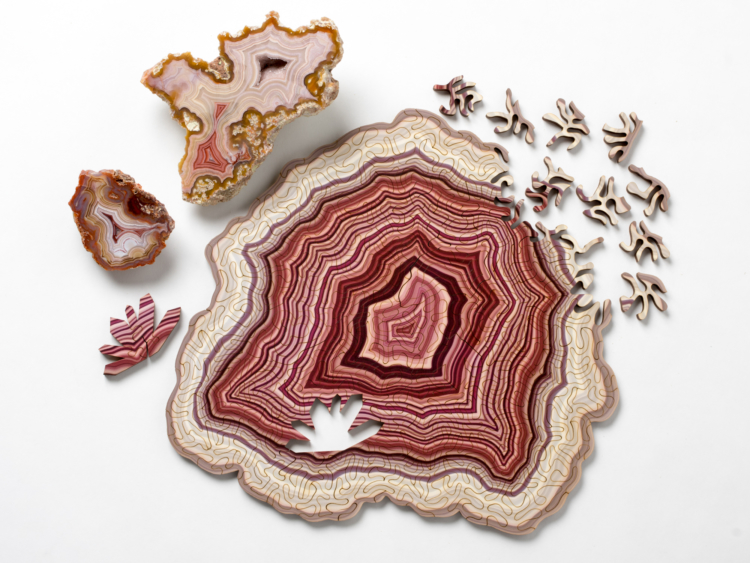
Nervous System is a generative art studio and one of their most viral projects is their geode jigsaw puzzles. Each puzzle has a unique computer-generated shape and pattern, resulting in the many types of geode puzzles. While each geode turns out unique, the process of computer generation is similar as they code it so that the rock used will grow progressively inwards and fill the chamber. Colors, characteristics, and growth rates are random which results in the unique puzzles. Each of the computer generated images represents a portion of the algorithmic agate.

What I admire most about this project is that its beautiful in its art form, but since its a puzzle it requires logical problem-solving skills. Most puzzles have an outcome that is a rectangular picture, so it is easy to establish the corners and the outside borders. However in this case you would have to work from inside to out, not having any easy puzzle pieces to go off from.

This video from Nervous System gives a summary of their geode puzzles from how they made them to what ta unique puzzle looks like.
A wholistic picture of the puzzle. The final result of the puzzle is a beautiful piece of art, but so many intricate pieces are needed to make it.
A closer look into the laser-cutted individual pieces needed for the geode jigsaw puzzle.
For more information on this specific project, click the link above to go to their blog about their jigsaw puzzles.

Emma N-M LO-03

Digital Stimulation by David McLeod

Piplines by David Leod (2015)

This parametric 3D fabrication project explores generative abstract forms. A digital dynamic stimulation was created to help inform what shapes to sculpt and what material should be used. I found this project to be inspirational because you can get lost in the forms created by the fluid movements. I also enjoyed how the artist used the digital stimulation and created sculptures to represent certain frames of the digital stimulation. There are algorithms used in the digital stimulation and with small tweaks to it, the stimulation can become drastically different. The algorithms were suppose to emulate objects in a turbulent situation. The creator’s artistic sensibilities manifest through interpreting the digital forms created and translating them into something physical (a sculpture). By using the final shapes to inform him on the texture treatment for the sculptures, each one is very different from the others, yet they come from the same place.