Looking Outwards 03: Computational Fabrication

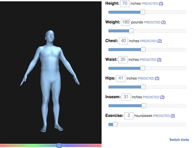
I think it is particularly interesting to link computational and parametric objects to living matter; such as nature or human. After reading professor Levin’s, I was really intrigued by how they digitally visualized a human body with different levers to control the width and length of each body part.

bodyvisualizer

Parametric 3D Form

I was interested in how each feature was correlated and dependent to one another and not completely independent, to make it a more accurate and realistic depiction of the actual human body. I have seen programs like this before, but each input for each body part could be changed completely on its own, allowing me to create a very unrealistic version of myself. I think that using programs like this would very much enhance the human life, in fields like fashion, medication, etc. I interpret this project as more of a scientific and technical approach than an artistically free one, but I think it is very interesting in ways how it can be of help in those various fields. If these kind of dependent parametric objects were created for other existences like animals or plants, I think that it will be a great way to determine and help sustain the natural environment as well.

Project-03: Dynamic Drawing

sketch
var angle = 0;
function setup() {
    createCanvas(600, 450);
    rectMode(CENTER);
}

function draw() {
    background(0);
    fill(255, 255, mouseY);
    // restrict mouseX to 0-400
    var m = max(min(mouseX, 400), 0);
    var size = m * 350.0 / 400.0;
    if (mouseX < width/2) {
        push(); 
        translate(150,200);
        rotate(radians(angle)); 
        rectMode(CENTER);
        rect(10 + m * 190.0 / 400.0, 200.0,
         size, size);
        pop();
        angle += 5;
} 

    else {
        rect(10 + m * 190.0 / 400.0, 200.0,
         size, size);
}

    fill(mouseX, 0, 255);
    size = 350 - size;
    rect(200 + m * 190.0 / 400.0, 200.0,
         size, size);


// } else if (mouseX > width/2) {background (0,0,200)}

}

Looking Outwards-03

Looking at Parametric world, I found myself particularly intrigued by a post by A Fractured Reality: this was a cross section of a mouse intestine has been stained with fluorescent dyes. With the dyes in place, it is easy to see how different parts of the cross section manipulates and comes together to form this complex geometry, creating this sense of parametric design. it was very interesting for me to see how life imitates art, even at the molecular scale. The individual who made this post is a physician who spent 3 years doing research in ophthalmology and 1 year working as a patient care technician.

“Glitch Reality”

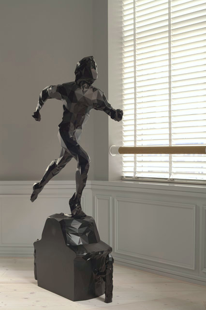
What do you think about when you hear the phrase “Glitch Reality”? Does a picture of a future world made out of robots and pixels pop up in your mind? Because for us glitch reality is not a future anymore but rather present, or reality as the name itself implies. British-Colombian artist Matthew Plummer-Fernández constructed a dimension variables sculpture called “Running Trophy” and the algorithms that generated that project were 3D prints software (SLS nylon), die, CNC-carved machining foam and black piano paint. This sculpture isn’t perfect since it contains chipped edges that were caused by the loss of data during the process of digitization and creation. In order to create the trophy, there was needed to be a 3D scanning of a running trophy which helped Plummer-Fernandez obtain all information about the shape of an object which later on was used to scale-up and create a trophy. The bulging shapes and the dents are what inspire me about this project since no human on planet Earth is perfect and this runner has its imperfections due to data loss which makes it flawed yet so humane at the same time. The creator’s artistic sensibilities manifest in the final form by adding life and beauty into the sculpture; many would assume that that nothing beautiful can be made using a 3D software due to chipped edges and simple design however simplicity is an art and the thought that a sculpture like that was made out of algorithm in the 3D software printing is simply unimaginable.

https://www.plummerfernandez.com/works/glitch-reality/

Matthew Plummer-Fernández, Glitch Reality – “Trophy Runner”, 2011

This imagine is of a sculpture from a Glitch Reality project called “Trophy Runner” that was made using a 3D printer software in 2011 by Matthew Plummer-Fernández.

Project 3: Dynamic Drawing

var maxHue = 70;
var currentHue = maxHue;


function setup() {
  createCanvas(800,400);
  background(100);

  colorMode(HSB, 350, 110, 110);
  var skyHue = currentHue;
  background(22, 0, 20);
}

function draw() {


  var c = width / 2;
  background(255);
  noStroke();
  var skyHue = currentHue;
  skyHue = map(mouseX, 0, width, 0, 270);
  for (var rectY = 0; rectY < 700; rectY += 10) {
    fill(skyHue, 50, map(mouseX, 0, width, 100, 0));
    rect(0, rectY, width, 250);
    skyHue++;
    fill(212, 0, 79, 0.08);
    rect(0, 400, width, 300);


  }

  sun();    

    fill(192,192,192);
    triangle(-200, 475, 170, 180, 700, 475);
    fill(160, 160, 160);
    triangle(80, 400, 680, 230, 900, 400);
    
}

function sun() {
  var diameter = height + 100;
  S = map(mouseX, 0, width, 45, 10);
  var mouseangle = map(mouseX, 0, width, PI, TWO_PI+ QUARTER_PI);
  var d1 = 10 + (sin(mouseangle) * diameter / 2) + diameter / 2;
  fill(50, 100, 175);
  ellipse(mouseX, d1 - 90, 90, 90);
  fill(0, 0, 0,);
  
}

LO: Computational Fabrication

Megumi Igarashi, or Rokudenashiko, which means “good-for-nothing kid,” made waves in the news when she was found guilty of obscenity in 2013 and 2014. This is because of the data distribution of her 3D model, “Pussy Boat,” molded after a scan of her own vagina. The vagina is a common motif in her art, as she tries to normalize the vagina in Japanese society. Many criticized the Japanese government for her arrest because of the hypocrisy, like how the Festival of the Steel Penis is held every year in Kawasaki, filled with phallic-shaped merchandise and food. Her studio was raided by police and they confiscated her more “realistic” art pieces. What’s left of her art is “Manko-chan,” a cute little character that is, well, a vagina. Still, it’s subversive how playful her art is when the conversation around female anatomy is shrouded in shame and stigma. Last year, the Japanese Supreme Court rejected her appeal for the obscenity charge. She will be fined ¥400,000 ($3,740).

https://www.japantimes.co.jp/news/2020/07/16/national/japan-top-court-rejects-vagina-kayak-artists-obscenity-appeal/

https://www.vice.com/en/article/ae5pvk/in-the-studio-with-japans-controversial-vagina-artist

Japanese artist jailed for vagina boat says outraged, vows legal fight |  Reuters.com
Megumi Igarashi with the “Pussy Boat.”
Japanese court rules vagina figurines 'pop art', not obscenity | Reuters
Igarashi and “Manko-chan” figurines.

My Inspiration – Week 3

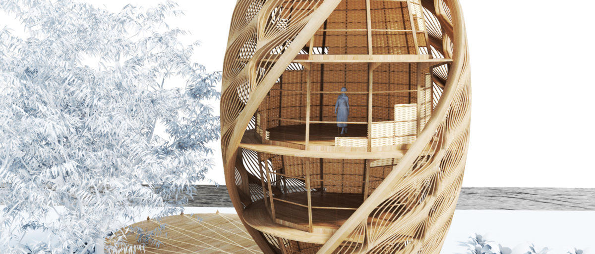
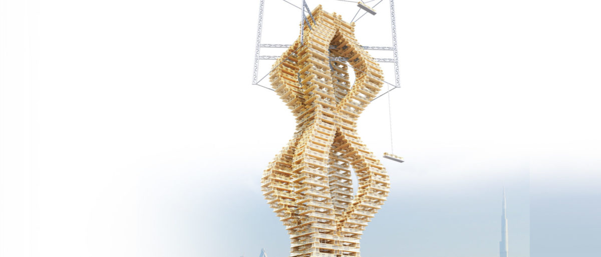
I really admire the Mamou Mani project because of its soft and modern-looking design. The unique shapes and curves of the different digital structures in his work create a futuristic style while also having enough simplicity to make the structures more realistic. Each one of his projects also has an intention behind it, whether it is to create a building that is more eco-friendly or a building that emphasizes the rich culture of the community that built it. A lot of the shapes in the buildings are looping and repeating throughout the construction, so parts of the algorithm are looping to create that consistent and patterned look. For example, in the ECOPODS project, the entire building is one looped grouping of code. You can tell that if the building were taller, the design would continue climbing upward with the spiraling pattern. The artist also seems to like to use flowy movements with his work, which are most evident in his DNA BlockChain Skyscraper.

Mamou Mani Projects

Mamou Mani’s Ecopod Project
Mamou Mani’s DNA Blockchain Skyscraper

Project 3: Dynamic Drawing

dynamic drawing
var angle = 0;

function setup() {
    createCanvas(600, 450);
    
}

function draw() {
    // change the background color from light -> dark blue as mouse top -> bottom of canvas
    if (mouseY < height/7) { 
        background (188, 210, 232); //lightest blue
    } else if (mouseY < (height/7)*2) {
        background (145, 186, 214);
    } else if (mouseY < (height/7)*3) {
        background (115, 165, 198);
    } else if (mouseY < (height/7)*4) {
        background (82, 138, 174);
    } else if (mouseY < (height/7)*5) {
        background (46, 89, 132);
    } else if (mouseY < (height/7)*6) {
        background (30, 63, 102);
    } else {
        background (23, 47, 77); //darkest blue
    }

    //a box at the center of the canvas
    stroke(0);
    strokeWeight(3);
    line(250, 175, 250, 275); //left border of box
    line(250, 175, 350, 175); //top border of box
    line(350, 175, 350, 275); //right border of box
    line(250, 275, 350, 275); //bottom border of box
    fill(79, 37, 37); //brown color for box
    rect(250, 175, 100, 100);

    //open side of box if mouse touches border
    if (mouseX < 250 & mouseY > 175 && mouseY < 275) { //if open left side
        line(200, 150, 250, 175);
        line(200, 300, 250, 275);
        var r = 255; //pink fill
        var g = 180;
        var b = 200;
        fill(r, g, b);
        circle(mouseX, mouseY, 300-mouseX); //small circle attached to mouse
        fill(r-mouseX, g-mouseX, b-mouseX); //opposite color from small circle
        circle(0, mouseY, mouseX); //large circle on the side of canvas

    } else if (mouseX > 350 & mouseY > 175 && mouseY < 275) { //if open right side
        line(350, 175, 400, 150);
        line(350, 275, 400, 300);
        //rectangle spin on center, change size and spin angle 
        if(mouseX > 350 & mouseX <450) {
            fill(235, 207, 52); //yellow
        } else {
            fill(52, 235, 116); //green
        }
        push();
        translate(350, 225);
        rotate(radians(angle));
        rectMode(CENTER);
        rect(50, 50, mouseX-300, mouseX-300); //size of rect increases as mouse goes to the right
        pop();
        if (mouseX > 350 & mouseX < 450){ //if on left side
            angle += 3; //rotate clock-wise
        } else { //if on right side
            angle -= 3; //rotate counter clock-wise
        }

    } else if (mouseY < 175 & mouseX > 250 && mouseX < 350) { //if open top side
        line(200, 150, 250, 175);
        line(350, 175, 400, 150);
        var circleX = 300;
        var circleY = 150;
        //let circle size depend on how close mouse is to circles
        var size = constrain(dist(mouseX, mouseY, circleX, circleY),0, 30); 
        fill(115, 105, 205); //fill purple
        circle(circleX, circleY, size); //first circle
        circle(circleX, circleY-30, size*2); //2nd circle
        circle(circleX, circleY-60, size); //3rd circle
        circle(circleX, circleY-90, size*2); //4th circle
        circle(circleX, circleY-120, size); //5th circle

    } else if (mouseY > 275 & mouseX > 250 && mouseX < 350) { //if open bottom side
        line(200, 300, 250, 275);
        line(350, 275, 400, 300);
        //random neon spike of lines that follows the mouse 
        stroke(255, 230, 0); //bright yellow
        line(287.5, 362.5, mouseX, mouseY);
        line(287.5, 362.5, mapx, mapy+180);
        line(287.5, 362.5, mapx+40, mapy);
        line(287.5, 362.5, mapx, mapy+200);

        var mapx = map(mouseX, 250, 350, 210, 310); //map to a shorter length
        var mapy = map(mouseY, 275, 450, 235, 410); //map to a shorter length
        
        stroke(122, 255, 105); //bright green
        line(287.5, 362.5, mapx, mapy);
        line(287.5, 362.5, mapx-130, mapy-50);
        line(287.5, 362.5, mapx-40, mapy-20);
        line(287.5, 362.5, mapx-130, mapy+150);
        line(287.5, 362.5, mapx-150, mapy-39);

        stroke(248, 59, 255); //bright purple
        line(287.5, 362.5, mapx*2, mapy*2);
        line(287.5, 362.5, mapx*1.1, mapy);
        line(287.5, 362.5, mapx, mapy+220);
        line(287.5, 362.5, mapx+50, mapy);
        line(287.5, 362.5, mapx-80, mapy);

        stroke(150, 255, 250); //bright blue
        line(287.5, 362.5, mapx*1.5, mapy);
        line(287.5, 362.5, mapx-195, mapy+239);
        line(287.5, 362.5, mapx-230, mapy+180);
        line(287.5, 362.5, mapx+10, mapy+50);
        line(287.5, 362.5, mapx, mapy+190);
        line(287.5, 362.5, mapx*0.2, mapy*2);

        stroke(255, 150, 217); //bright pink
        line(287.5, 362.5, mapx-20, mapy);
        line(287.5, 362.5, mapx-100, mapy);
        line(287.5, 362.5, mapx-170, mapy+20);
    }

}

The idea behind this drawing is a box that reveals different changing elements depending on where you put your mouse. The most challenging part of this project was figuring out how to make the elements change based on their interaction with mouseX and mouseY. I had to do some trial-and-error to get the effects that I wanted.
Project 3 Dynamic Drawing

sketch

//Michelle Dang (mtdang) section D
var r = 0; //red
var g = 0; //green
var b = 0; //blue 
var s = 2; //stroke weight

var f = 0; //fill color black

function setup() {
    createCanvas(450, 600);
    background(0);


    }

function draw() {
    translate(width/2, height/2); // center origin
    fill(f, 50);
    stroke(r, g, b, 100); 
    strokeWeight(s);
    rotate(mouseX); //rotate ellipse
    ellipse(0, 0, mouseY, mouseX); //elipse size based on mouse
    ellipse(0, 0, mouseX, mouseY); //elipse size based on mouse
    ellipse(0, 0, 30,30); // center ellipse for clear indication of stroke weight change

    mouseX -= .5;


    if (mouseX < 450 & mouseX > 0 && mouseY < 600 && mouseY > 0) { //when mouse is farthest form center, make ellipse purple
        r=127;
        g=0;
        b = 255;
    }
        if (mouseX<405 & mouseX > 45 && mouseY < 540 && mouseY > 60 ) { //blue stroke
        r = 0;
        g = 0;
        b = 255;
    }
    if (mouseX < 360 & mouseX > 90 && mouseY < 480 && mouseY > 120) { //green stroke
        r = 0;
        g = 255;
        b = 0;
 }  if (mouseX < 315 & mouseX > 135 && mouseY < 420 && mouseY > 180) { //orange stroke
        r = 255;
        g = 128;
        b = 0;
    }
    if (mouseX < 270 & mouseX > 180 && mouseY < 360  && mouseY > 240) { // when mouse is closest to center, make ellipses red 
        r = 255;
        g = 0;
        b = 0;
    
    }
}

    function mousePressed() {
      s = random(1, 20); // if mouse is pressed, randomly change strokeWeight
    }


Looking Outwards 3

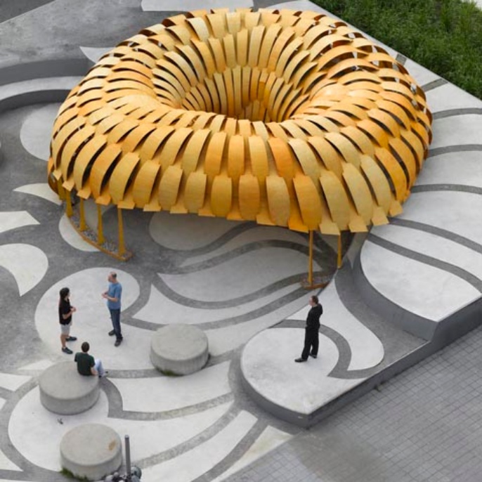
Institute for Computational Design (ICD) and the Institute of Building Structures and Structural Design (ITKE) have used an interdisciplinary approach of biomimetic, computing, and robots to create research pavilions between 2010-2021. The first pavilion they created intentionally computes the design according to the characteristics and constraints of the material choices and physical form. Because they used birch plywood, they considered the elasticity of the wood and how bending flat strips that were robotically manufactured can connect the modular pieces. I am impressed with how the connections of the modules allow reinforcement of each other — it seems that adhesives or additional reinforcers were not used. I wonder how they were able to test out the structural integrity pavilion when computing the design — how did they know that the pavilion would not collapse? How could different materials affect the design?

https://www.itke.uni-stuttgart.de/research/icd-itke-research-pavilions/icd-itke-research-pavilion-2010/