Looking Outward – 03

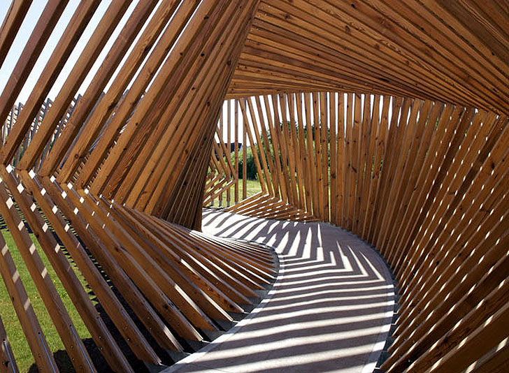
A computational project that inspires me is an architectural project done by Thilo Frank called EKKO. This project is located in Denmark and is a continuous walkway that consists of 200 wooden frames that incrementally change dimensions to create a long and contorted structure. The structure was computational in its design as the exterior shape was shaped by keyframes and the computer filling in the frames in between. The design also incorporates microphones within the wood to record and playback the sounds of the people walking through the structure. This type of work is done with parametric modeling in which the set of processes to create design is laid out by the person and the computer interprets it in many different ways. The artists’ sensibilities manifest themselves in the experience that one has inside the structure and the elaborate design the artist laid out in order to give the user a feeling of what the artist senses.

https://www.dezeen.com/2012/10/29/ekko-installation-by-thilo-frank/

Dynamic Drawing

sketch

function setup() {
    createCanvas(480,640);
    background(0);
}

function draw() {
    var shapeWidth;
    shapeWidth = Math.abs(mouseX - 240) / 2 + 80;
    background(0);
    fill(255, mouseY / 2.5, 0);
    ellipse(240, 180, shapeWidth, 200);
    fill(0, 255, mouseY / 2.5);
    ellipse(120, 440, shapeWidth, 200);
    fill(mouseY / 2.5, 0, 255);
    ellipse(360, 440, shapeWidth, 200);
}

I drew three circles that change color and width based on the mouse position. First I drew the circles and changed the colors, and then I decided that wasn’t complicated enough. Now they look super cool!

LookingOutwards-03

I love how this project is an intersection between an organic tree / physical origami and computer generated art. The structure is an interesting mix of structured and unstructured. Its shapes are relatively simple ellipses, but they’ve been stacked to look like a tree. Even without knowing that it’s supposed to be a tree, the shape is relatively clear. The design is super cool and futuristic! I wonder how much of the tree was computer generated / 3D printed and how much was made by hand. Since it’s origami, maybe some of it was made organically. I also have no idea what material may have been used. The creator does a great job blending generative art and traditional origami. The tree is very cool and futuristic, and I’d love to see other works by this artist.

^^The super cool tree :O

Project 3 – Dynamic Drawing

Orbits

//changing RGB colors
var R = 0;
var G = 0;
var B = 0;

//assigned in mousePressed to print and save color to rect
var tempR = 255;
var tempG = 255;
var tempB = 255;

function setup() {
    createCanvas(450, 640);
    background(255);
}

function mousePressed() {
    print('------------------')
    print('R: ' + R.toString())
    print('G: ' + G.toString())
    print('B: ' + B.toString())

    //stores current RGB untill mousePressed again
    tempR = R;
    tempG = G;
    tempB = B;

}
function draw() {

    var lim = 140; //map(mouseX, 0, width, 0, 255);
    var diff = 255-lim;
    var index = 0;

    background(R, G, B);

    //color save
    noStroke();
    fill(tempR, tempG, tempB);
    square(10, 10, 100);

    //color fader
    if (mouseY < height/6) {
        index = map(mouseY, 0, height/6, lim, 255)
        R = 255;
        G = lim;
        B = index;
    } else if ((mouseY >= height/6) & (mouseY < 2*height/6)) {
        index = map(mouseY, height/6, 2*height/6, 0, diff)
        R = 255 - index;
        G = lim;
        B = 255;
    } else if ((mouseY >= 2*height/6) & (mouseY < 3*height/6)) {
        index = map(mouseY, 2*height/6, 3*height/6, lim, 255)
        R = lim;
        G = index;
        B = 255;
    } else if ((mouseY >= 3*height/6) & (mouseY < 4*height/6)) {
        index = map(mouseY, 3*height/6, 4*height/6, 0, diff)
        R = lim;
        G = 255;
        B = 255 - index;
    } else if ((mouseY >= 4*height/6) & (mouseY < 5*height/6)) {
        index = map(mouseY, 4*height/6, 5*height/6, lim, 255)
        R = index;
        G = 255;
        B = lim;
    } else {
        index = map(mouseY, 5*height/6, 6*height/6, 0, diff)
        R = 255;
        G = 255-index;
        B = lim;
    }

    //orbits
    var deg = map(mouseY, 0, width, 0, 360);
    var cirSize = 10;
    var cirX = mouseX/2 //x dist from mouse
    var cirY = mouseY/2 //y dist from mouse

    var sunY = map(mouseY, 0, height, -0.4*height, 1.4*height);
    fill(255, 113, 124);
    ellipse(width/2, sunY, 700);

    fill(255-R, 255-G, 255-B);
    translate(mouseX, mouseY);
    ellipse(cirX, cirY, cirSize);
    rotate(radians(deg));
    ellipse(cirX, cirY, cirSize);
    rotate(radians(deg));
    ellipse(cirX, cirY, cirSize);
    rotate(radians(deg));
    ellipse(cirX, cirY, cirSize);
    rotate(radians(deg));
    ellipse(cirX, cirY, cirSize);
    rotate(radians(deg));
    ellipse(cirX, cirY, cirSize);

    scale(mouseY/height);
    ellipse(cirX, cirY, cirSize);
    rotate(radians(deg));
    ellipse(cirX, cirY, cirSize);
    rotate(radians(deg));
    ellipse(cirX, cirY, cirSize);
    rotate(radians(deg));
    ellipse(cirX, cirY, cirSize);
    rotate(radians(deg));
    ellipse(cirX, cirY, cirSize);
    rotate(radians(deg));
    ellipse(cirX, cirY, cirSize);

}

LO3 – Computational Fabrication

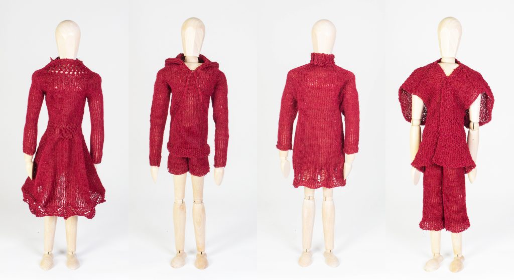
For this week’s looking outwards blog post, I decided to look into a project from MIT CSAIL on Machine-Knit Garments. The project contributes designed a workflow that allows a user to design a template, then turn that template into a time function such that a knitting machine can turn it into a garment. This approach doesn’t require a user to design complex 3D objects, as the algorithm turns 2D templates into machine code. According to the project team, this is meant to allow for interactive editing of the shape of the garment. I was particularly drawn to this project because I had never heard of CNC knitting machines. I’ve worked with routers and 3D printers before, but computer-controlled knitting machines open up a whole other world of computational fabrication. Additionally, the software the users built allows for user interaction with the design, which I think also has the potential of turning into very interesting pieces of art.

Knit Sketching

Project-03: Dynamic Drawing

My Project

//sets up RGB values for color change;
var colorR = 236;
var colorG = 47;
var colorB = 19;
var colorR2 = 22;
var colorG2 = 167;
var colorB2 = 233;
//sets up angle variable that moves center rectangle;
var angle = 1;
//sets up direction variable that determines which direction said rectangle rotates;
var dir = 1;

function setup() {
    createCanvas(650, 400);
    background(220);
    //text("p5.js vers 0.9.0 test.", 10, 15);
}

function draw() {
    //creates a background that changes color dependant on which;
    //side of the canvas the mouse is on;
    background(colorR, colorG, colorB);
    //makes the rectangles based on the center of themselves; 
    rectMode(CENTER);
    //allows the rectangles to change color dependant on which;
    //side of the cnavas the mouse is on;
    fill(colorR2, colorG2, colorB2);
    //creates the 2 rectangles nearer to the perimeter of the canvas;
    //they are opposite each other in direction and location;
    //they increase in size when the mouse is on the right side and decrease when on the left;
    rect(constrain(mouseX, 50, 600), 50, max(50, min(mouseX, 300)), max(50, min(mouseX, 300)));
    rect(max(600 - mouseX, 50), 350, max(50, min(mouseX, 300)), max(50, min(mouseX, 300)));
    //I used existing RGB values to make the center rectangle have dynamic color change as well;
    fill(colorR, colorG2, colorB);
    //allows for the center rectangle to rotate;
    push();
    translate(325, 200);
    rotate(radians(angle));
    rect(0, 0, max(250-mouseX, 50), max(250-mouseX, 50));
    pop();
    angle = angle + (dir*1);
    //changes the color between color depending on which side the mouse is on;
    if ( ((colorR != 22) & (colorG != 167) 
        && (colorB != 233)) && mouseX > 325 ){
        colorR -= 1; 
        colorG += 1; 
        colorB += 1;
    }
    else if ( ((colorR != 236) & (colorG != 47) 
        && (colorB != 19)) && mouseX < 325 ){
        colorR += 1;
        colorG -= 1;
        colorB -= 1;
    }
    if ( ((colorR2 != 22) & (colorG2 != 167) 
        && (colorB2 != 233)) && mouseX < 325 ){
        colorR2 -= 1; 
        colorG2 += 1; 
        colorB2 += 1;
    }
    else if ( ((colorR2 != 236) & (colorG2 != 47) 
        && (colorB2 != 19)) && mouseX > 325 ){
        colorR2 += 1;
        colorG2 -= 1;
        colorB2 -= 1;
    }
    //changes the dir variable and thereby the direction of the center rectangle;
    //dependant on which side of the canvas the mouse is on;
    if (mouseX < 325){
        dir = -1;
    }
    else{
        dir = 1;
    }

}


I originally had something more complex but I changed it to something simpler. And I like how it is now.

LO3: Computational Fabrication

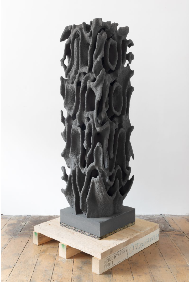
Daniel Widrig’s Instances (2019)

For this week’s LO, I will talk about Daniel Widrig’s Instances (2019) – pictured above.


Daniel Widrig is a London based Architect and Designer who uses Digital Outlets to create. He has his own Studio and has designed many Buildings with Architect Zaha Hadid. He has also won many awards for design.


As for Widrig’s Instances, what I like about it is how it looks. The Sculpture/Artwork gives off a very futuristic and almost alien like vibe. However, from what I have seen of Computational Fabrication, that is a common feature.


That is not to say I would not have it in my house. I would.


I guess I admire its compactness and what seems to be the fact that it can be remade quickly? But also, uniqueness in that there should only be one of it.


I have no idea of the algorithms of which the Widrig used to create this work, but my guess is one that is complex but has constraints in the x, y, and z directions.


As for Widrig’s sensibilities, the Sculpture shows off how far into the future his work is.


To end, I like the Sculpture and its practicality. I would like to know how it was made.


Links to Daniel Widrig, this specific work, and his other works (Instances is labeled 158-156).

Dynamic Drawing

sketch

var angle = 80;

function setup() {
    createCanvas(600,450);
    background(220);
    text("p5.js vers 0.9.0 test.", 10, 15);
}

function draw() {
	background(mouseX,mouseY, 155);

	//leaves
	/*This part of the code draws two ellipses of grass green color. I used push() and pop()
	commans to remember new positions of two ellipses due to translation and rotation*/
	if(mouseX>300) {
		push();
	    noStroke();
	    fill(124, 252, 0);
	    translate(300, 300); //chnages a (0, 0) point to (300, 300)
	    rotate(radians(50)); //rotates an ellipse 50 degrees in radians clockwise
	    ellipse(66, 20, 30, 70);
	    rotate(radians(-83)); //rotates an ellipse 80 degrees in radians counterclockwise
	    ellipse(-30, 20, 25, 50);
	    pop();
    }

	//This part of the code draws dark green stem of a flower
	noStroke();
	fill(0, 100, 0);
	rect(298, 230, 5, mouseX);
    
    //This part of the code restricts mouseX to 0-115
	var m = max(min(mouseX, 115), 0);
    var size = m * 350.0 / 400.0;

    /*I used push() and pop() commands to remember new positions of petals becuase I used 
    translation and rotation. I drew 9 petals of a flower by rotating them 40 degrees in radians
    from previous petal's location*/
    push();
    stroke(255);
    strokeWeight(1);
    fill(55, mouseX, mouseY, 150); /*This changes the color of petals in regards with (x,y)
    location and it has 150 transparency*/
    translate(300, 225); //changes a (0, 0) point to (300, 225)
    rotate(radians(40));
    ellipse(0 + m * 190.0 / 400.0, 0, 100, 35); 
    rotate(radians(40));
    ellipse(0 + m * 190.0 / 400.0, 0, 100, 35);
    rotate(radians(40));
    ellipse(0 + m * 190.0 / 400.0, 0, 100, 35);
    rotate(radians(40));
    ellipse(0 + m * 190.0 / 400.0, 0, 100, 35);
    rotate(radians(40));
    ellipse(0 + m * 190.0 / 400.0, 0, 100, 35);
    rotate(radians(40));
    ellipse(0 + m * 190.0 / 400.0, 0, 100, 35);
    rotate(radians(40));
    ellipse(0 + m * 190.0 / 400.0, 0, 100, 35);
    rotate(radians(40));
    ellipse(0 + m * 190.0 / 400.0, 0, 100, 35);
    rotate(radians(40));
    ellipse(0 + m * 190.0 / 400.0, 0, 100, 35);
    pop();
    
    //This part of the code draws a stigma of a flower
    noStroke();
    fill(150, mouseX, mouseY); /*This changes the color of stigma in regards with (x,y)
    location*/
    circle(300, 225, 15);	

    //This part of the code draws 3 cluds that are moving with regards of mouseX
    noStroke();
    fill(max(mouseX, mouseY)); /*This changes clouds' color by choosing the greater value from
    mouseX and mouseY locations*/
    ellipse(mouseX, 50, 70, 35);
    ellipse(mouseX+25, 40, 50, 20);
    ellipse(mouseX-25, 60, 50, 20);
  
    ellipse(mouseX+120, 80, 70, 35);
    ellipse(mouseX+145, 70, 50, 20);
    ellipse(mouseX+95, 90, 50, 20);

    ellipse(mouseX+240, 25, 70, 35);
    ellipse(mouseX+265, 15, 50, 20);
    ellipse(mouseX+215, 35, 50, 20);
   
    //This part of the code draws grass
    fill(55, 143, 80); 
    noStroke(); 
    //first moving part of grass in regards with mouseX
    triangle(mouseX-540, 450, mouseX-530, 400, mouseX-520, 450);
    triangle(mouseX-520, 450, mouseX-510, 400, mouseX-500, 450);
    triangle(mouseX-500, 450, mouseX-490, 400, mouseX-480, 450);
    triangle(mouseX-480, 450, mouseX-470, 400, mouseX-460, 450);
    triangle(mouseX-460, 450, mouseX-450, 400, mouseX-440, 450);
    triangle(mouseX-440, 450, mouseX-430, 400, mouseX-420, 450);
    triangle(mouseX-420, 450, mouseX-410, 400, mouseX-400, 450);
    triangle(mouseX-400, 450, mouseX-390, 400, mouseX-380, 450);
    triangle(mouseX-380, 450, mouseX-370, 400, mouseX-360, 450);
    triangle(mouseX-360, 450, mouseX-350, 400, mouseX-340, 450);
    triangle(mouseX-340, 450, mouseX-330, 400, mouseX-320, 450);
  
    //constant part of grass
    triangle(200, 450, 210, 400, 220, 450);
    triangle(220, 450, 230, 400, 240, 450);
    triangle(240, 450, 250, 400, 260, 450);
    triangle(260, 450, 270, 400, 280, 450);
    triangle(280, 450, 290, 400, 300, 450);
    triangle(300, 450, 310, 400, 320, 450);
    triangle(320, 450, 330, 400, 340, 450);
    triangle(340, 450, 350, 400, 360, 450);
    triangle(360, 450, 370, 400, 380, 450);
    triangle(380, 450, 390, 400, 400, 450);

    //second moving part of grass in regards with mouseX
    triangle(mouseX-930, 450, mouseX-920, 400, mouseX-910, 450);
    triangle(mouseX-910, 450, mouseX-900, 400, mouseX-890, 450);
    triangle(mouseX-890, 450, mouseX-880, 400, mouseX-870, 450);
    triangle(mouseX-870, 450, mouseX-860, 400, mouseX-850, 450);
    triangle(mouseX-850, 450, mouseX-840, 400, mouseX-830, 450);
    triangle(mouseX-830, 450, mouseX-820, 400, mouseX-810, 450);
    triangle(mouseX-810, 450, mouseX-800, 400, mouseX-790, 450);
    triangle(mouseX-790, 450, mouseX-780, 400, mouseX-770, 450);
    triangle(mouseX-770, 450, mouseX-760, 400, mouseX-750, 450);
    triangle(mouseX-750, 450, mouseX-740, 400, mouseX-730, 450);

    
    if(mouseX>width/2){ //checks if mouseX is on the right side of a screen
    	translate(500, 100); //changes a (0, 0) point to (500, 100)

    	var mapX = map(mouseX, 100, 300, 250, 250); //remaping a mouseX from one range to another.
        var mapY = map(mouseY, 100, 0, 100, 200); //remaping a mouseY from one range to another.
        
        //This part of the code draws sunrays that will follow mouseX and mouseY
        strokeWeight(5);
        stroke(255,165,0); //orange
        line(0, 0, mapX, mapY);
        line(0, 0, mapX-20, mapY-20);
        line(0, 0, mapX-80, mapY-80);
        line(0, 0, mapX-140, mapY-140);
        line(0, 0, mapX-200, mapY-200);

        stroke(218,165,32); //golden rod
        line(0, 0, mapX, mapY);
        line(0, 0, mapX+20, mapY-20);
        line(0, 0, mapX+80, mapY+80);
        line(0, 0, map-140, mapY+140);
        line(0, 0, mapX+200, mapY+200);

        stroke(255,215,0); //gold
        line(0, 0, mapX*1, mapY*1);
        line(0, 0,  mapX*1.5, mapY*1.5);
        line(0, 0,  mapX*2, mapY*2);
        line(0, 0,  mapX*0.5, mapY*0.5);
        line(0, 0,  mapX, mapY*1.5);
        line(0, 0, mapX*1.5, mapY);

        stroke(255,69,0); //orange red
        line(0, 0, mapX-50, mapY+20);
        line(0, 0, mapX+200, mapY);
        line(0, 0, mapX-30, mapY+55);
        line(0, 0, mapX*0.2, mapY+100);
        line(0, 0, mapX-20, mapY+130);
        line(0, 0, mapX*1.4, mapY/1.2);

        //This part of the code draws a sun
    	strokeWeight(3);
    	stroke(255);
    	fill(249, 215, 28);
    	circle(0, 0, 70);  
    }    
} 


During the process of my work, I thought of things that change their position or their colors all the time in real world and I came up with a small drawings of a flower, clouds, grass, sun and sky. I followed the idea that flowers grow and clouds move which made it easier to follow the procedures.
Project 3: Dynamic Drawing

wpf-dynamic-drawing
function setup() {
    createCanvas(600, 450);
}

function draw() {
    var positionY = constrain(mouseY, 80, 400); //relative Y position for everything that is constrained so the sun doesnt shoot off into the sky etc
    background(139,214,241);
    fill(21,8,29, mouseY - 80); //transitions background to night sky by decreasing transparency with mouseY position
    rect(0,0,600,300);

    var rainbowAlpha = map(constrain(mouseY,80,400), 80, 250, 255, 0); //variable to control transparency of the rainbow as it goes down

    noStroke();
    
    fill(255,0,0,rainbowAlpha); //the rainbow: red
    ellipse(300, positionY + 100, 700, 200);
    fill(254,98,48,rainbowAlpha); //orange
    ellipse(300, positionY + 120, 700, 200);
    fill(255,246,2,rainbowAlpha); //yellow
    ellipse(300, positionY + 140, 700, 200);
    fill(1,179,2,rainbowAlpha); //green
    ellipse(300, positionY + 160, 700, 200);
    fill(4,1,119,rainbowAlpha); //blue
    ellipse(300, positionY + 180, 700, 200);
    fill(35,3,114,rainbowAlpha); //violet
    ellipse(300, positionY + 200, 700, 200,);
    fill(139,214,241); //"clear" ellipse that is the same color as the day background
    ellipse(300, positionY + 220, 700, 200,); 
    fill(21,8,29, mouseY - 80); //"clear" ellipse that tranistions to night sky same why the regular background does
    ellipse(300, positionY + 220, 700, 200); 


    fill(255,246,2); //sun
    circle(150, positionY - 50, 50);

    fill(241,222,150); //moon
    circle(390, positionY - 325, 30);

    fill(233,233,255,mouseY - 250); //stars
    circle(40,96,10);
    circle(250,15,10);
    circle(330,62,10);
    circle(470,340,10);
    circle(580,70,10);
    circle(346,54,10);
    circle(200,30,10);
    circle(475,120,10);
    circle(175,60,10);
    circle(275,115,10);
    circle(430,50,10);
    circle(20,20,10);
    circle(100,40,10);
    circle(270,50,10);
    circle(80,130,10);
    circle(500,25,10);
    circle(400,100,10);
    circle(150,85,10);
    circle(500,55,10);


    var positionX = constrain(mouseX,35,565);

    fill(141,196,39); //green "field"
    rect(0,300,600, 150);

    var oppositeX = map(positionX, 0, 600, 600, 0);

    fill(103,62,16); //left dog
    ellipse(positionX, 350,30,15); //body
    circle(positionX + 15, 345,15); //head
    ellipse(positionX-10,355, 5,8); //leg
    ellipse(positionX + 10, 355, 5, 8); //leg
    ellipse(positionX-15,350,15,5); //tail
    triangle(positionX+9,340,positionX+12,335,positionX+16,340); //ear
    triangle(positionX+14,340,positionX+17,335,positionX+20,340); //ear
    fill(0);
    circle(positionX+16,343,2); //eyes
    circle(positionX+19,343,2);

    fill(103,62,16); //right dog
    ellipse(oppositeX, 390,30,15); //body
    circle(oppositeX - 15, 385,15); //head
    ellipse(oppositeX + 10,395, 5,8); //leg
    ellipse(oppositeX - 10, 395, 5, 8); //leg
    ellipse(oppositeX + 15,390,15,5); //tail
    triangle(oppositeX - 9,380,oppositeX - 12,375,oppositeX - 16,380); //ear
    triangle(oppositeX - 14,380,oppositeX - 17,375,oppositeX - 20,380); //ear
    fill(0);
    circle(oppositeX - 16,383,2); //eyes
    circle(oppositeX - 19,383,2);


}

I had difficulty with this project. I had a hard time coming up with something to draw. Once I had an idea I really enjoyed coming up with ways as to how I could incorporate dynamic elements into it. One thing, in particular, I am proud of is figuring out that the map function can work backwards, with the higher value being the start point and the lower value being the stop point, which allows you to invert the value of a variable in a sense.

LO-03: Computational Fabrication

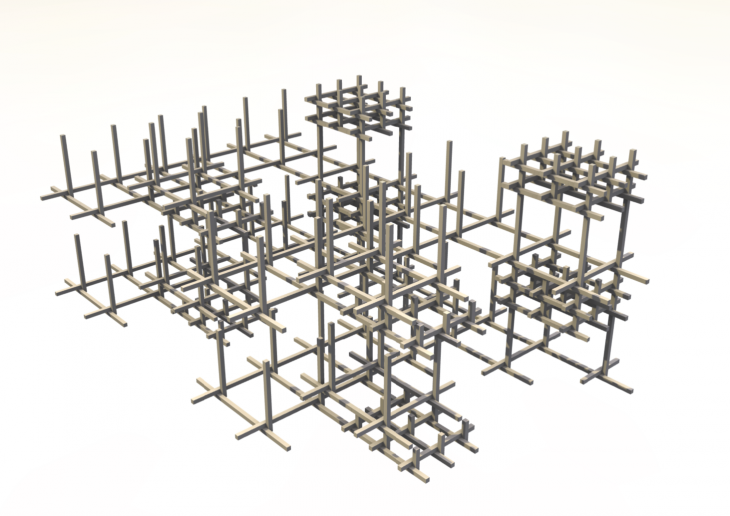
The project I chose for this blog is a KUKA robotic arm parametric cuboid grid fabrication. Posted to the journal for the Institute for advanced architecture of Catalonia, this project utilizes KUKA robotic arm technology to build a wooden grid with variable density out of wooden battens and pins. Modules for the grid can be assembled (cutting, drilling, positioning) entirely by the robot arm. Modules with varying programmed densities can be connected together to complete complex structures. I like this project because of the simplistic method it uses to create structures. By programming the KUKA arm to your own personal parameters, an infinite number of structures can be built and used for the construction of art, architecture, models, etc. As shown in the attached image, the robot arm is able to build grids with complex densities while using a singular building strategy by altering the lengths of the battens and the space between connections.

ROBOTIC FABRICATION – CUBOID GRID
INSTITUTE FOR ADVANCED ARCHITECTURE OF CATALONIA, BARCELONA
MARCH 29, 2016

This is an example of a completed grid.
“Speculating on the final form shows how density can be controlled throughout the structure.”