Yingying Yan LookingOutwards-03

Axon of the building, showing how it responded to the context.

Zaha Hadid is the first female winner of the Pritzker Architecture Prize. She is also one of my favorite architects. She is known for using the computer and making parametric designs. Galaxy Soho, in Beijing, is one of the most representative projects by Zaha Hadid.

Closer view of the flow of the form.

The design is responsive to the Rings, or the site context. I am most admire about the fact that Zaha was able to control every single curve of the building, and resulted in a piece of art that similar to a Chinese courtyard. The building is used as the office and retail space. It is basically four continuous, flowing volume. I could not find any related algorithm, but I know that Grasshopper is a software that can make building’s like that. It really shows me how powerful computer is these days.

Floor plan of the building, showing how it is one flowing volume.

Mimi Jiao Project 3 Dynamic Drawing

sketch.js

var defaultBG = 0;
//to inverse line/background colors when key is pressed
var whiteLines = 255;
var blackLines = 0;

function setup() {
    createCanvas(640, 480);
}

function draw() {
    background(defaultBG);
    //changes background color when mouse hovers over top/bottom of page
    if (mouseY >= 3 * height / 4) {
        background(255, 0, 0);
    }else if (mouseY <= height / 4) {
        background(0, 0, 255);
    };
    noFill();
    stroke(0, 255, 0);
    strokeWeight(1);
    ellipse( width / 2, height / 2, 50, 50);
    //green rectangle going across page
    fill(0, 255, 0);
    noStroke();
    rect(mouseX - width * .75, 50, 250, 10);
    noFill();
    strokeWeight(1);
    stroke(whiteLines);
    //three swinging lines
    line(width - mouseX, 130, 30, 50);
    line(width - mouseX + 30, 140, 30, 50);
    line(width - mouseX + 60, 150, 30, 50);
    //change color of rectangle outline and make text appear
    //if mouse is pressed
    if (mouseIsPressed) {
        strokeWeight(2);
        stroke(255, 54, 258);
        stroke(whiteLines);
        strokeWeight(.5);
        textFont('Courier New');
        text("ok ok ok ok ok ok ok", 50, 100);
        stroke(255, 54, 258);
    };
    //vertical lines on top
    strokeWeight(1);
    rect(width / 4, 100, 50, 70);
    stroke(whiteLines);
    strokeWeight(1);
    line(500, mouseY, 500, mouseY + 200);
    line(505, mouseY, 505, mouseY + 200);
    line(510, mouseY, 510, mouseY + 200);
    line(515, mouseY, 515, mouseY + 200);
    line(520, mouseY, 520, mouseY + 200);
    line(525, mouseY, 525, mouseY + 200);
    line(530, mouseY, 530, mouseY + 200);
    line(535, mouseY, 535, mouseY + 200);
    line(540, mouseY, 540, mouseY + 200);
    //vertical lines on bottom
    stroke(0,255,0);
    line(502, mouseY * 1.5 + 150, 502, mouseY * 1.5 + 410);
    line(507, mouseY * 1.5 + 160, 507, mouseY * 1.5 + 480);
    line(512, mouseY * 1.5 + 170, 512, mouseY * 1.5 + 480);
    line(517, mouseY * 1.5 + 180, 517, mouseY * 1.5 + 480);
    line(522, mouseY * 1.5 + 190, 522, mouseY * 1.5 + 480);
    line(527, mouseY * 1.5 + 200, 527, mouseY * 1.5 + 510);
    line(532, mouseY * 1.3 + 50, 532, mouseY * 1.3 + 510);
    line(537, mouseY * 1.3 + 50, 537, mouseY * 1.3 + 510);
    //thin rectangle blocks moving across page on bottom
    noStroke();
    fill(whiteLines);
    rect(width - mouseX, 400, 100, 5);
    rect(width - mouseX * 1.5, 400, 60, 5);
    rect(width - mouseX * 2.5, 400, 40, 5);

    rect(width - mouseX + 70, 425, 100, 3);
    rect(width - mouseX * 1.5 + 70, 425, 60, 3);
    rect(width - mouseX * 2.5 + 70, 425, 40, 3);
    //makes text follow mouse
    text("stop following me! :((", mouseX, mouseY);
    translate(mouseX, mouseY);
    noStroke();
    //if mouse isn't clicked, text and circles will show
    if (mouseIsPressed === false) {
        fill(0, 0, 255);
        ellipse(20, 20, 20, 20);
        ellipse(40, 40, 20, 20);
        textFont('Courier New');
        fill(255, 0, 0);
        text("no no no no no", 50, 100);
        stroke(255, 54, 258);
        fill(0, 0, 255);
    }
}
//inverses black and white colors when key pressed
function keyTyped() {
    if (defaultBG > 0) {
        defaultBG = 0;
        whiteLines = 255;
    }else {
        defaultBG += 255;
        whiteLines -= 255;
        fill(defaultBG);
    }
}

Like many other people, I initially had no idea what to do since it was so open ended. I started off by making random shapes and lines, and since I naturally prefer certain colors, what I made began to resemble this (shown below!) I made for fun last week. This project ended up being a continuation and exploration of that. Since I am interested in bringing narrative elements to everything I made, I created a mini dialogue that results from mouse interaction.

Tanvi Harkare – Looking Outwards – 03

One of the projects discussing computational digital fabrication is part of the MAAD program at CMU. In addition to fabrication, the program consists of architectural robotics and ecological thinking. There are multiple different studios that you can choose from in this program, but the one that interests me the most deals with experimentation with new and different materials that explore contemporary design techniques. The design process starts with using some type of algorithm to create a parametric design. Next, this can be translated into either a physical model or a 2D drawing. Some digital fabrication tools that are helpful to completing projects include 3D modeling software, robotic arms, laser cutting machines, and a CNC router. 

A 3D model created using computational design software

As an architecture undergraduate student at CMU, I’m interested in any future paths I might be able to take. The importance of computational fabrication is increasing greatly in architecture schools; we are taught computational fabrication as early as the second year of the undergraduate program. For example, we had to create an object using fiberglass and resin that was designed using a computational program called Grasshopper, which works through the 3D modeling software Rhino. 

An example of Rhino 3D modeling software and a Grasshopper script


Project 03 Liz Maday

liz maday project 3 sketch

//Elizabeth Maday
//emaday@andrew.cmu.edu
//Section A
//emaday

function setup() {
    createCanvas(640, 480);
}

function draw() {
    var distance = int(dist(width/2, height/2, mouseX, mouseY));
    var vineTipX = 0;
    var vineTipY = 0;
    var x = width/2;
    var y = height/2;
    var r = 0;
    var g = 170;
    var b = 245;
    var eyeSize = 5;

    //make color get darker as mouse moves up
    if (mouseY < y) { 
    	r -= 0; 
    	g -= distance/2; 
    	b -= distance/2; 

    //make color lighter as mouse moves down
    } else if (mouseY > y) {
    	r += distance/2; 
    	g += distance/2; 
    	b += 0; 
    }
    background(r, g, b);

    //make vines move left and right
    if (mouseX > x) {
    	vineTipX += distance;
    } 
    if (mouseX < x) {
    	vineTipX -= distance;	
    }

    //make vines move up and down
    if (mouseY > y) {
    	vineTipY += distance;
    }
    if (mouseY < y) {
    	vineTipY -= distance;
    }

    //change eyeSize
    if (mouseY < y) {
    	eyeSize = 4;
    }
    if (mouseY > y) {
    	eyeSize = 10;
    }

    //draw triangles left
    noStroke();
    fill(0, 97, 85);
    triangle(0, 50, 0, 85, 200 + vineTipX, 65 + vineTipY);
    triangle(0, 100, 0, 135, 240 + vineTipX, 115 + vineTipY);
    triangle(0, 150, 0, 185, 280 + vineTipX, 165 + vineTipY);
    triangle(0, 200, 0, 235, 320 + vineTipX, 215 + vineTipY);
    triangle(0, 250, 0, 285, 360 + vineTipX, 265 + vineTipY);
    triangle(0, 300, 0, 335, 320 + vineTipX, 315 + vineTipY);
    triangle(0, 350, 0, 385, 280 + vineTipX, 365 + vineTipY);
    triangle(0, 400, 0, 435, 240 + vineTipX, 415 + vineTipY);

    //draw triangles right
    fill(0, 192, 58);
    triangle(550 + vineTipX, 40 + vineTipY, 640, 15, 640, 50);
    triangle(510 + vineTipX, 90 + vineTipY, 640, 65, 640, 100);
    triangle(460 + vineTipX, 140 + vineTipY, 640, 115, 640, 150);
    triangle(410 + vineTipX, 190 + vineTipY, 640, 165, 640, 200);
    triangle(460 + vineTipX, 240 + vineTipY, 640, 215, 640, 250);
    triangle(510 + vineTipX, 290 + vineTipY, 640, 265, 640, 300);
    triangle(550 + vineTipX, 340 + vineTipY, 640, 315, 640, 350);
    triangle(600 + vineTipX, 390 + vineTipY, 640, 365, 640, 400);

    //draw sun around mouse
    fill(255, 188, 0);
    stroke(255, 188, 0);
    strokeWeight(7);
    line(mouseX, mouseY, mouseX + 30, mouseY + 30);
    line(mouseX, mouseY, mouseX - 30, mouseY - 30);
    line(mouseX, mouseY, mouseX + 30, mouseY - 30);
    line(mouseX, mouseY, mouseX - 30, mouseY + 30);
    line(mouseX, mouseY, mouseX + 42.5, mouseY);
    line(mouseX, mouseY, mouseX - 42.5, mouseY);
    line(mouseX, mouseY, mouseX, mouseY + 42.5);
    line(mouseX, mouseY, mouseX, mouseY - 42.5);
    strokeWeight(2);
    ellipse(mouseX, mouseY, 40, 40);

    //draw sun face
    stroke(0);
    line(mouseX - 10, mouseY + 3, mouseX + 10, mouseY + 3);
    fill(0);
    ellipse(mouseX - 8, mouseY - 5, eyeSize, eyeSize);
    ellipse(mouseX + 8, mouseY - 5, eyeSize, eyeSize);

    //draw fish
    var dist2 = (0, 100, mouseX, mouseY);
    noStroke();
    ellipseMode(CENTER);
    fill(0);
    triangle(dist2 + 13, 400, dist2 + 25, 385, dist2 + 25, 415); //bottom fish tail
    fill(255, 73, 177);
    ellipse(dist2, 400, 30, 30);  //bottom fish body
    fill(0);
    ellipse(dist2 - 5, 400, 5, 5); //bottom fish eye
    fill(0);
    ellipse(dist2 + width/2 + 13, 80, 17, 12); //top fish tail
    fill(255, 121, 0);
    ellipse(dist2 + width/2, 80, 30, 30); //top fish body
    fill(0);
    ellipse(dist2 - 5 + width/2, 80, 5, 5); //top fish eye
}


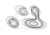
With this project, I liked how I was able to play around with a concept. The sun image represents sunlight entering an underwater scene, and all the other elements react to its position.

Yoo Jin Shin-Project-03-Dynamic-Drawing

Project-03

// Yoo Jin Shin
// Section D
// yoojins@andrew.cmu.edu
// Project-03

var eyeSize = 50;

// top pupil
var pupilSizeL = 5;
var pupilSizeR = 6;

// bottom pupil
var pupilSize2L = 10;
var pupilSize2R = 10;
var pupilLeftX2 = 128;
var pupilLeftY2 = 164;
var pupilRightX2 = 210;
var pupilRightY2 = 166;

var faceHeight = 300;
var faceR = 244;
var faceG = 240;
var faceB = 132;

function setup() {
    createCanvas(640, 480);
}
 
function draw() {
    // gradient background that changes with mouse position
    var backgroundR = mouseX * 0.39;
    var backgroundG = mouseY * 0.53;
    var backgroundB = 255;
    background(backgroundR, backgroundG, backgroundB);
    noStroke();

    // face width that enlarges from 10 to width as mouseX moves right
    fill(faceR, faceG, faceB);
    ellipse(180, 180, constrain(mouseX, 10, width), faceHeight);

    // left eye
    fill(0);
    ellipse(140, 160, eyeSize, eyeSize);

    // left pupil that follow mouse within left eye boundary
    fill(255);
    ellipse(constrain(mouseX, 125, 153), constrain(mouseY, 150, 168), pupilSizeL, pupilSizeL);
    ellipse(pupilLeftX2, pupilLeftY2, pupilSize2L, pupilSize2L);

    // left eyebrow
    fill(backgroundR, backgroundG, backgroundB);
    rect(125, 123, 25, 7, 3);

    // right eye
    fill(0);
    ellipse(220, 160, eyeSize, eyeSize);

    // right pupil that follow mouse within right eye boundary
    fill(255);
    ellipse(constrain(mouseX, 207, 230), constrain(mouseY, 150, 168), pupilSizeR, pupilSizeR);
    ellipse(pupilRightX2, pupilRightY2, pupilSize2R, pupilSize2R);

    // right eyebrow
    fill(backgroundR, backgroundG, backgroundB);
    rect(210, 123, 25, 7, 3);

    // mouth
    fill(backgroundR, backgroundG, backgroundB);
    arc(180, 180, 20, 40, TWO_PI, PI);

    // "SNOW" text that enlarges from 20 to mouseX as mouse moves right
    fill(255);
    noStroke();
    textSize(20 + mouseX / 4);
    textFont('Helvetica');
    text('SNOW', constrain(mouseX, 0, width), 390);

    // background snow that follows mouse position
    push();
    translate(mouseX + 1, mouseY + 1);
    rotate(radians(20));
    fill(255);
    noStroke(255);
    ellipse(mouseX + 5, mouseY + 5, 8, 8);
    ellipse(mouseX + 10, mouseY + 50, 3, 3);
    ellipse(mouseX + 80, mouseY + 50, 10, 10);
    ellipse(mouseX + 50, mouseY + 200, 20, 20);
    ellipse(mouseX + 20, mouseY + 100, 8, 8);
    ellipse(mouseX + 100, mouseY + 90, 14, 14);
    ellipse(mouseX + 52, mouseY + 100, 8, 8);
    ellipse(mouseX + 102, mouseY + 200, 3, 3);
    ellipse(mouseX + 88, mouseY + 300, 10, 10);
    ellipse(mouseX + 502, mouseY + 400, 20, 20);
    ellipse(mouseX + 202, mouseY + 430, 8, 8);
    ellipse(mouseX + 102, mouseY + 240, 14, 14);
    ellipse(mouseX - 5, mouseY - 5, 8, 8);
    ellipse(mouseX - 10, mouseY - 50, 3, 3);
    ellipse(mouseX - 80, mouseY - 50, 10, 10);
    ellipse(mouseX - 50, mouseY - 200, 20, 20);
    ellipse(mouseX - 20, mouseY - 100, 8, 8);
    ellipse(mouseX - 100, mouseY - 90, 14, 14);
    pop();
}

I modified my variable face to make it more interactive by adding features like face shape, color, text, and snow that change as the mouse position changes. I think it’s interesting how depending on the face width, the face can range from looking like a fish to a pancake.

ChristineSeo-LookingOutwards-03-SectionC

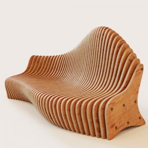
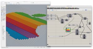
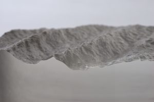
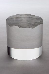
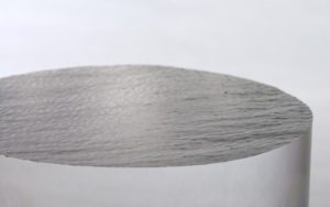
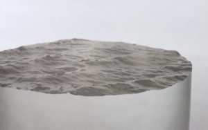
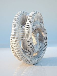
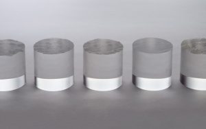
This work was created by David Bowen over a course of a few days which involved a drone running ArduPilot software; it hovered 30 meters above Lake Superior and captured still images of the water’s surface. The surface ripples changed every time the weather was different and Bowen captured these images and converted them into three-dimensional displacement maps. The information was carved with a CNC router into a series of transparent acrylic cylinders.

David Bowen was influenced by the relationship between natural and mechanical systems: he had other projects that related to this topic. His previous project, Underwater, was a large scale, real-time installation that captured the surface of waves through hundreds of servo-motors. I believe he was inspired by the topic and his previous works that made him continue his research and thus create another work. Through his projects, he wanted to “provide an immersive mechanical perspective of a natural, dynamic and ageless phenomenon.”

In my previous Looking Outwards assignments, I researched a couple that were similar to this topic. I am very fascinated by the idea of nature coming together with technology to create beautiful pieces. It was very intriguing that he used clear acrylic to cut this out because it displays the delicacy of the water through the material: it captures the beauty of nature in a man made work. However, he only made 5 of these cylinders and I wish he made a room filled with them to display the vast scale of a ocean/lake. Overall, I am very interested in CNC routers because I am an art student and I am working as a monitor to help out with students to use CMU’s CNC router in Doherty Hall. I’ve actually created works with the machine before and will keep working to create more meaningful art!

http://www.creativeapplications.net/objects/the-obverse-box-deru-fuses-sound-light-and-artifact/

Nina Yoo Section E LookingOutwards- 03

Andrew Kudless takes basic geometry alongside nature in order to create designs that seem to use less materials, but also create strong structures. A lot of his work can be used as a replacement/upgrade for current objects we have now as well as buildings. I am inspired as a designer because being able to create unique patterns while also considering the logistics of it and using the nature’s strongest forms, is something that is difficult to achieve. His simple yet mathematical designs creates another pathway for other designers to consider what nature and years or math research has to offer. The algorithm that generates this work derives from patterns found in nature and relates it to geometrical patterns and tries to find a way where the two creates the best results for a certain object. Andrew Kudless expresses art in his work by choosing which patterns go together and whether or not he decides to create a complicated structure or creates a structure that provides the minimum in order to convey his idea.

https://www.pinterest.com/matsys/computational-design/


Anthony Ra – Looking Outwards – 03

Wood-Skin Video 

Demonstrating flexibility of wood-skin

Wood-Skin is a fabrication firm that attempts to use ideas of digital fabrication and typical building materials to build new composite materials and technology. It is described as the most flexible 3D surfaces for architecture and design.

Wood-skin can be altered into whatever function and decor is wanted

The process begins with a digital model through a CAD file. What also makes this project unique is the variety of materials that can be utilized such as wood, metal, acrylic, etc. In reality, wood-skin is fabricated with the combination of pliable nylon and polymer mesh.

table made with modules of wood-skin

The composite materials are generated from a digital file to a CNC mill where a series of modules of the same algorithm can be realized by fabricating them. They can also be altered based on thickness, pliability, and even overall shape.

wood-skin can be altered into different triangular patterns

The benefit of this computative fabrication is the elimination of a complex understructure that may be needed for complex forms. One can alter the pattern in however manner they like and can pave the way as using composite materials an option for building material.


LO3 – Alexander Chen

Digital Grotesque is the name of two separate installations that are pieces of architectural works that resemble the works of Spanish architect Antonion Gaudi. These rooms are 3D printed and were entirely made from algorithms. I admire this project because it takes something that is seemingly very mathematical and calculated like algorithms and make it into something very beautiful and artistic. Replicating architectural styles of the past that well is something already commendable, but it also implies further scientific creations. For example, this kind of structure probably would have taken forever to make in the time that this type of architecture was the norm. However, this took only one month to print which while is a long time to print, it is nothing compared to the years of the original.

Romi Jin – Looking Outwards 03

Having taken an architecture course about computation fabrication (Fundamentals of Computational Design), I have some familiarity in this field. After researching a few examples, HG’s Opening Chronometry interested me. In the class I took, I created many parametric pavilions similar to that of HG Architecture’s. The process is essentially translating a shell into a larger shell — placing double-layered cones into a mathematical pattern created using Grasshopper.
Grasshopper-created parametric system of units to assemble a pavilion.
(above) Grasshopper-created parametric system of units to assemble a pavilion.

It is interesting to think how a small-scale structure built using simple units can potentially be transformed into a large-scale home or building using a modular system. Parametric systems use a strict logic to create its design; however, this logic can be flexibly manipulated into visually different forms for different purposes as well. Computational fabrication can also be used to help build cheap, sustainable and easy-to-assemble homes, as well as speed up the process and lessen the effort placed into the whole process of construction.