Ed Catmull, from Pixar, invented the texture mapping technique in 1974. It is regarded as a breakthrough in 3D Computer Graphic. I admire this because it evokes sense of touching by sight and gives more vivid feeling to a flat object. The technique is widely used in animation. It brings life to millions of cartoon characters. Texture coordinates(generated by some functions) are added to the original vertex. Besides that, colors are changed accordingly. Several techniques are evolved including forward texture mapping, inverse texture mapping, affine texture mapping, etc. It is still in progress for it is not capable of accomplishing some complicated surfaces vividly.
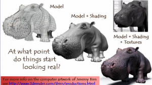
More texture mapping knowledge from CMU
Month: October 2016
Jun seo Hahm is an animator, designer, and media artist based in Seoul, South Korea. This piece is a short film, entitled “Walking Follows Form”. I like the film because of the way it uses the modelling process to inform the animation. The way each model moves is based on it’s structure or shape, and this means that each character moves in really strange and humorous ways. I like the idea of using loose sets of rules to make art, and this is a good example of that.
Hahm’s fascination with cartoony forms and visuals really comes across in the film, along with a strong interest in the forms of the 3d objects. His models are also incredibly smooth, avoiding the sharp geometric style that some other new media artists are drawn to.
I don’t know what exact tools Hahm uses to create his work, but I’d imagine a 3d modelling program like Blender.
zhuoyinl- project05 wallpaper
//Zhuoying Lin
//section a
//zhuoyinl@andrew.cmu.edu
//project

function setup() {
    createCanvas(600, 700);

}


function draw() {
    background(240);

    //monster
    var mx = random(-50,100);//origin x
    var my = random(30,100);//origin y
    var sy = 200;//y spacing
    var sx = 200;//x spacing
    for (var y = 0; y<7; y++) {
        if (y%2==0) {
            for (var x = 0; x<5; x++) {
                monster(mx+x*sx, my+y* (sy*sqrt(3)/2));
            }
        } else {
            for (var x = 0; x<5; x++) {
                monster(mx+sx/2+x*sx, my+y* (sy*sqrt(3)/2));
            }
        }
    }
    noLoop();

    //duck
    var dx = random(0,50);//origin x
    var dy = random(30,50);//origin y
    var sy = 150;//y spacing
    var sx = 250;//x spacing
    for (var y = 0; y<7; y++) {
        if (y%2==0) {
            for (var x = 0; x<5; x++) {
                duck(dx+sx/2+x*sx, dy+y* (sy*sqrt(3)/2));
            }
        } else {
            for (var x = 0; x<5; x++) {
                duck(dx+x*sx, dy+y* (sy*sqrt(3)/2));
            }
        }
    }
    noLoop();

}

function monster(mx, my) {//draw monster
    push();
    translate(mx, my);
    stroke(137,78,115);
    strokeWeight(5);
    line(25, -25, 25, 0);//ear1
    line(45, -25, 35, 0);//ear2
    line(30, 30, 85, 40);//tail
    stroke(244,179,220);
    strokeWeight(30);
    line(10, 0, 50, 0);//monster head
    strokeWeight(5);
    line(35, 40, 35, 60);//foot1
    line(45, 40, 45, 60);//foot2
    line(55, 40, 55, 60);//foot3
    line(65, 40, 65, 60);//foot4
    strokeWeight(50);
    line(50, 10, 50, 30);//monster body
    fill(255);
    noStroke();
    ellipse(22, 0, 15, 15);//left eye
    ellipse(42, 0, 15, 15);//right eye
    fill(0);
    noStroke();
    ellipse(20, 0, 5, 5);//eyeball1
    ellipse(40, 0, 5, 5);//eyeball2
    pop();
}

function duck(dx, dy) {//draw duck
    push();
    translate(dx, dy);
    stroke(255, 183, 0);
    strokeWeight(5);
    line(-15, 60, -15, 85);//foot1
    line(-5, 60, -5, 85);//foot2
    stroke(154, 231, 217);
    strokeWeight(40);
    line(0, 0, 0, 30);//neck
    strokeWeight(40);
    line(-30, 40, 0, 40);//body
    strokeWeight(10);
    line(-55, 40, -30, 40);//tail
    stroke(255, 183, 0);
    strokeWeight(7);
    line(10, 7, 25, 7);//mouse
    line(10, 14, 25, 14);//mouse
    fill(255);
    noStroke();
    ellipse(0, 0, 10, 10);//eye
    fill(0);
    noStroke();
    ellipse(1, 0, 5, 5);


    pop();
}
For this wallpaper, I used ‘random’ command to generate a little bit different patterns each time it is opened, and I tried to make the grid hexagon to add some interest to the grid.

mreyes-looking outwards 05-Sublime Moments
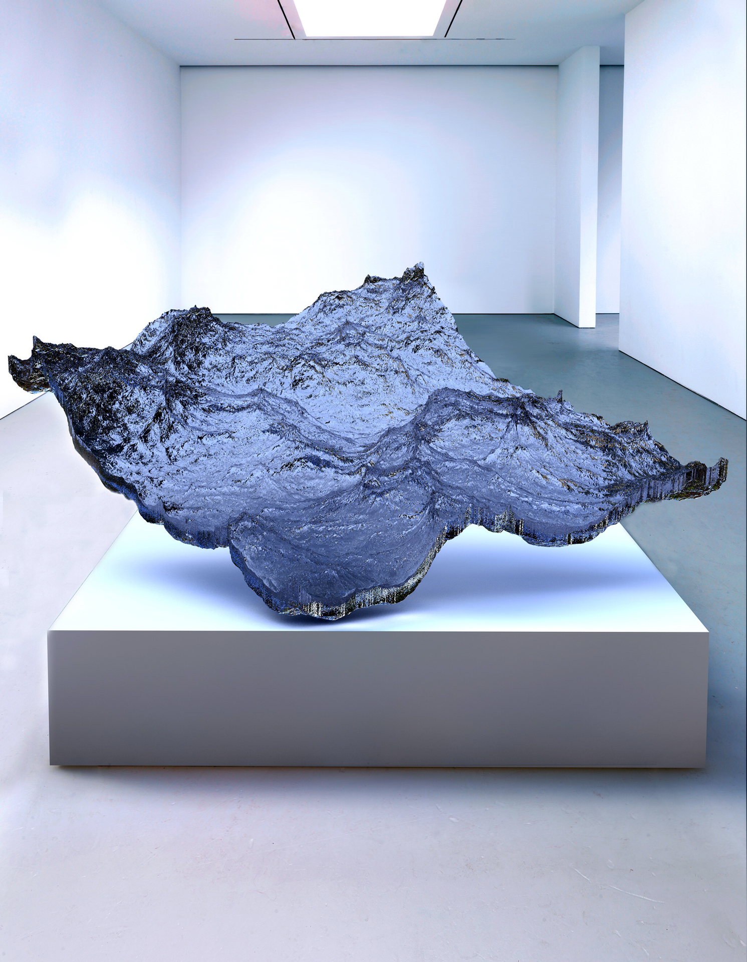
Eyal Gever, Sublime Moments, 2014
In his show, Sublime Moments all of Eyal Gever’s pieces have two parts to them. An complex computer simulated animation, and then a 3 foot sculpture of that animation. Gever volunteered to be in the Israel Defense Forces’ computer R&D unit, where he programed computer graphics to simulated possible outcomes. This was the foundation for him eventually developing his own software for his art. In an interview with Beautiful Decay he said “Using my own proprietary 3D physical simulation technologies, I have developed computational models for physical simulation, computer animation, and geometric modeling. Combining applied mathematics, computer science, and engineering…”
I admire this body of pieces because, I usually find hyperrealism (in both painting and sculpture) to be impressive but, ugly. However with Gever’s work I found his subject matter interesting as well as his execution and the forms he chooses to depict. The collection of pieces is enticing to look at as the forms suggest a movement but also give hint to a bigger motion yet to come. Gever Manages to capture the ominous potential along with a beauty and serenity of natural forms in a poetic juxtaposition.

Project-05
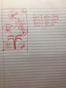
I was inspired by Lilly Pulitzer’s famous prints for this project. I spent a few hours looking through her prints and identifying the key aspects in them. They all have a beach theme, use bright colors, and are relatively simple in the patterns. To create the code, I made functions for each of the different elements and then called them within a for loop in the draw function. The only exception was the wave function which I called in the setup so that it would act more like a background than an element in the foreground.
Preliminary Sketch:
//Naomi Shimada
//Section D
//nshimada@andrew.cmu.edu
//Project-05

   var spacing = 100;


function setup() {
    createCanvas(800,600);
    background(150,225,249);
    wave(0,100);
    wave(0,300);
    wave(0,450);
}

function draw() {
for (var i = 0; i<=8; i++){
	star(i+ i*spacing+50,190);
	palmTree(i+ i*spacing-50,40);
	star(i+ i*spacing+50,490);
	beachBall(i + i*spacing+10,360);
}
}


function palmTree(x,y){
	push();
	translate(x,y);
	fill(250,9,162);
	stroke(135,0,36);
	strokeWeight(0);
	rect(x,y,25,80);
	fill(229,77,174);
	strokeWeight(12);
	line(x,y-12,x-20,y-16); //first half of lower left palmleaf
	line(x-20,y-16,x-45,y); //second half of lower left palmleaf
	line(x+25,y-12,x+45,y-16); //first half of lower right palmleaf
	line(x+45,y-16,x+70,y); //second half of lower right palmleaf
	strokeWeight(0);
	ellipse(x+17,y-8,20,20); //leftmost coconut
	ellipse(x+25,y+8,20,20); //lowermost coconut
	ellipse(x+30,y-5,20,20); //rightmost coconut
	strokeWeight(12);
	line(x,y-32,x-20,y-36); //first half of upper left palmleaf
	line(x-20,y-36,x-45,y-25); //second half of upper left palmleaf
	line(x+25,y-32,x+45,y-36); //first half of upper right palmleaf
	line(x+45,y-36,x+70,y-25); //second half of upper right palmleaf
	pop();
}

function star(x,y){
	push();
	strokeWeight(0);
    fill("Yellow");
    ellipse(x,y,20,50);   //x = 150, y = 100

    push();
    translate(x+10,y);
    rotate(45);
    fill("Yellow");
    ellipse(20,0,20,50);
    pop();

    push();
    translate(x+20,y+40);
    rotate(15);
    fill("Yellow");
    ellipse(0,0,20,50);
    pop();

    push();
    translate(x,y+43);
    rotate(0);
    fill("Yellow");
    ellipse(0,0,20,50);
    pop();

    push();
    translate(x-30,y+33);
    rotate(225);
    fill("Yellow");
    ellipse(20,0,20,50);
    pop();

    push();
    translate(x-12,y+35);
    rotate(180);
    fill("Yellow");
    ellipse(0,0,20,50);
    pop();
    pop();
}

function beachBall(x,y){
	fill(253,55,85);
	noStroke();
    ellipse(x,y,60,60);
}

function wave(x,y){
    for (var x = 0; x < width; x = x + 1) {
        stroke(11,11,249);
        strokeWeight(5);
        point(x, y - 50 * sin(radians(x)));
        stroke(8,70,117);
        strokeWeight(5);
        point(x, y - 50 * cos(radians(x)));
    }
}
zhuoyinl-Looking Outwards

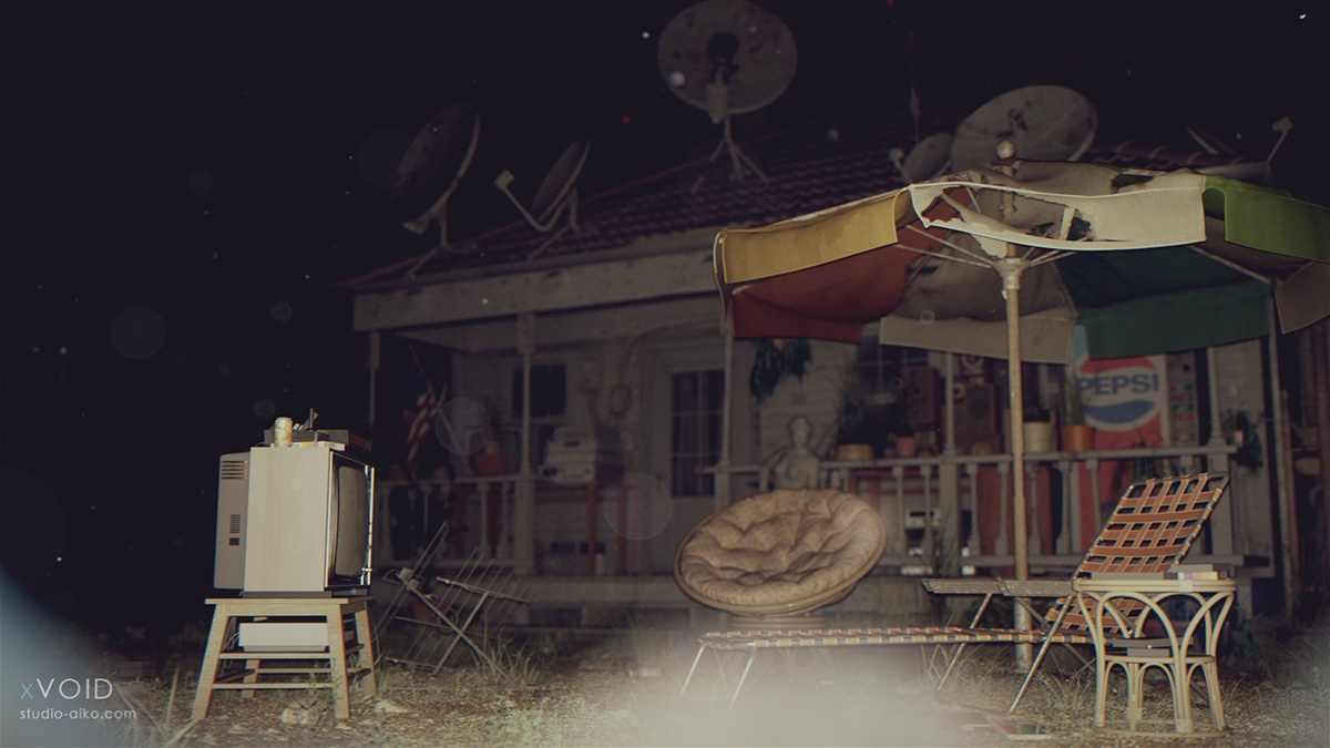
These Hyper-Realistic 3D computer graphic rendering is inspired by sci-fi and horror films and from locations of abandoned places which could be a great environment for making film story lines to occur. It is made by xVOID studio. They made around 14140 objects in the scene and used art CG 3D software such as 3D Studio Max, VRay, MODO, ZBrush, and Marvelous Designer. I found this project amazing because it simulate the environment so detailed, and they made 3D models to create this scene so that it could render scenes in different condition and viewer could get a 360 view of the objects. I found this extremely smart because in the architecture field, the simulation and graphic indication for clients is significantly important and such way of indication is rather comprehensive and impressive. For architecture student like me, 3D Max and VRay is no strangers but the way the author using different images and materials to render objects is amazing.
sajohnso-project-05
/*
*Sadie Johnson
*15-104 Section C
*sajohnso@andrew.cmu.edu
*Project-05
*This program draws wallpaper
*/
function setup() {
    createCanvas(800, 600);
    background('#F9F4F0');
}

function draw() {

for(var y=0; y<600; y+=200){
	for(var x=0; x<800; x+=200){
		drawPattern(x, y);
	}

}
}

function drawPattern (x, y){
	//BASE OF FLOWERS
		noStroke();
		fill('#FED1D6');
		ellipse(x+50,y+110,40,40); //small, leftmost flower
		ellipse(x+120,y+140,70,70); //biggest flower
		ellipse(x+115,y+65,30,30); //small, rightmost flower

	//INSIDE OF FLOWERS
		fill('#F497AA');
		ellipse(x+40,y+110,15,20); //small, leftmost flower
		ellipse(x+124,y+154,50,40); //middle of biggest flower
		ellipse(x+120,y+63,15,15); //middle of rightmost

	//LEAVES
		//bottom left grouping
			strokeWeight(6);
			stroke("#AFDDC3");
			line(x+67, y+130, x+50, y+150);
			strokeWeight(9);
			line(x+67, y+130, x+63, y+165);
			line(x+69, y+130, x+80, y+180);
		//top left leaf grouping
			strokeWeight(11);
			line(x+55, y+83, x+30, y+70);
			line(x+80, y+100, x+60, y+50);
			line(x+80, y+100, x+120, y+90);
			strokeWeight(15);
			line(x+80, y+100, x+90, y+25);
}
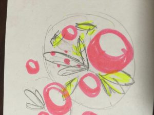
The most time-consuming part of this process was actually drawing the flower design, and not making the design repeat. It didn’t come out quite as floral as I had planned, but it’s aesthetically pleasing anyways.
Liu Xiangqi-Project-05
// Liu Xiangqi xiangqil@andrew.cmu.edu Section A Project-05

function setup() {
    createCanvas(600, 600);
    background(0);
    noLoop();

}


function draw() {
    var y = 0;
    var x = 0;
    for (y = 0; y + 50 < height - 50; y += 100){
        for (x = 0; x + 50 < width - 50; x += 100){
            //draw the roses
            fill(255);
            ellipse(50+x, 50+y, 10, 10);
            stroke(255, 77, 77);
            strokeWeight(6);
            noFill();
            for(var i = 1; i < 11; i ++){
                if (i%4 == 1) {
                    arc(50+x, 50+y, 4*i + 12.5, 4*i + 12.5, 0, HALF_PI);
                }else if (i%4 == 2) {
                    arc(50+x, 50+y, 4*i + 20, 4*i + 20, HALF_PI, PI);
                }else if (i%4 == 3) {
                    arc(50+x, 50+y, 4*i + 27.5, 4*i + 27.5, PI, PI+HALF_PI);
                }else{
                    noFill();
                    arc(57+x, 45+y, 4*i + 5, 4*i + 5, PI+HALF_PI, TWO_PI+QUARTER_PI);
                }
            }
            //draw the leaves
            fill(204, 255, 153);
            noStroke();
            beginShape();
            vertex(50+x, 80+y);
            curveVertex(50+x, 80+y);
            curveVertex(80+x, 100+y);
            curveVertex(90+x, 120+y);
            curveVertex(80+x, 110+y);
            curveVertex(50+x, 80+y);
            vertex(50+x, 80+y);
            endShape();
        }
    }

}
Jinhee Lee; Looking Outwards 05
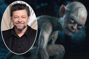
Gollum (pictured right), played by Andy Serkis (pictured left) in Lord of the Rings (2001-2003), and The Hobbit: An Unexpected Journey (2012), both directed by Peter Jackson.
Being that this blog post is about images rather than animation, I will talk about how Gollum’s appearance was rendered, though I will reference the latter in regards to The Hobbit.
Gollum’s appearance I believe is a rare achievement amongst CGI characters (even in modern films), as it incorporates several elements to create the character other than CGI, combining, to name a few, the 3D model with sculpted models as reference, motion capture with Serkis’ facial expressions, and Serkis’ physical presence on the set to help his fellow actors react believably.
According to this article, Bay Raitt and his team at Weta Digital created a system “which implemented 964 control points on Gollum’s face,” allowing detailed control of his facial expressions. To summarize, this system was used to animate Gollum’s face and a 3D model was drawn over the rest of Serkis’ body during recording.
The additional technique used in The Hobbit is particularly interesting in that it essentially gives Gollum a “living” skeleton, muscles, fascia, etc. to further enhance his lifelike appearance. As for the algorithms, I believe that the individual body elements are calculated to react to Serkis’ nuances in facial expression, in order to save the trouble of having to animate every single frame by hand.
Looking Outwards-05
The stunning images in James Cameron’s Titanic captivated audiences when it came out. While Cameron and his production team built half of the Titanic, for the iconic scoping shots, a 3d rendering of the full RMS Titanic was needed. Digital Domain, Cameron’s own CG company, did the majority of the effects and even went so far as to create new ones. Titanic was the first time that motion capture was used so algorithms had to be created to translate the movement of actors to the 3d animation. In addition, the full length iconic shots of the ship itself were mostly produced through animation. While a lot of the ship had been physically built, animators had to add extra sections to the ship and sometimes even render the whole ship.
I suppose that the algorithms created to produce the work dealt with looking at the movement of real ships, flags, people, etc and then animating the scenes appropriately. I don’t know how the animators would control the camera angles with the ship, but I assume that keeping the animation consistent while changing the camera angles was a big obstacle.
![[OLD – FALL 2016] 15-104 • COMPUTING for CREATIVE PRACTICE](../../../../wp-content/uploads/2020/08/stop-banner.png)
