LO: Computational Fabrication

While looking through the different projects of digital fabrication, one specific project from Marius Watz caught my attention. I really admire Chainmail by Watz because it looked so complex I had to really look into it to see how it was made. When I looked carefully at the artwork, it was basically made out of many chains that were connected by hollow rectangles. I think it’s interesting how Watz created an artwork that looks very complex, but the artwork itself is just chains connected together. I suppose the artwork is a parametric object because it is made out of repetitive shapes. Watz’s artworks are mostly geometric shapes that repeat each other to create something very complex. I feel that Watz really captured his artistic sensibilities in this artwork because he repeats a simple rectangular shape to create a very organic shape. The artwork itself is very round, however, it is made out of rectangular shapes.

Chainmail by Marius Watz

Dynamic Drawing

sketch

function setup() {
    createCanvas(480,640);
    background(0);
}

function draw() {
    var shapeWidth;
    shapeWidth = Math.abs(mouseX - 240) / 2 + 80;
    background(0);
    fill(255, mouseY / 2.5, 0);
    ellipse(240, 180, shapeWidth, 200);
    fill(0, 255, mouseY / 2.5);
    ellipse(120, 440, shapeWidth, 200);
    fill(mouseY / 2.5, 0, 255);
    ellipse(360, 440, shapeWidth, 200);
}

I drew three circles that change color and width based on the mouse position. First I drew the circles and changed the colors, and then I decided that wasn’t complicated enough. Now they look super cool!

LookingOutwards-03

I love how this project is an intersection between an organic tree / physical origami and computer generated art. The structure is an interesting mix of structured and unstructured. Its shapes are relatively simple ellipses, but they’ve been stacked to look like a tree. Even without knowing that it’s supposed to be a tree, the shape is relatively clear. The design is super cool and futuristic! I wonder how much of the tree was computer generated / 3D printed and how much was made by hand. Since it’s origami, maybe some of it was made organically. I also have no idea what material may have been used. The creator does a great job blending generative art and traditional origami. The tree is very cool and futuristic, and I’d love to see other works by this artist.

^^The super cool tree :O

Project 3: Dynamic Drawing

sketch

var angle = 0
function setup() {
    createCanvas(450, 600);
    background(0);
}

function draw() {
    if (mouseY < height / 2){ //determines color based on mouse's vertical side of canvas
        background ("black")
    }
    else if (mouseY > height / 2) {
        background (135, 188, 222)
    }
    //if (mouse X < width / 2) {
      //background (255, 190, 11)

    noStroke();
    fill("white") // circle moves up and down
    ellipse(225, mouseY, mouseY, mouseY)


    ellipse(mouseX, 300, mouseX, 10) // ellipses moves side to side and gets longer
    ellipse(mouseX, 20, mouseX, 10)
    ellipse(mouseX, 580, mouseX, 10)
    ellipse(mouseX, 40, mouseX, 10)
    ellipse(mouseX, 560, mouseX, 10)
    ellipse(mouseX, 60, mouseX, 10)
    ellipse(mouseX, 540, mouseX, 10)
    ellipse(mouseX, 320, mouseX, 10)
    ellipse(mouseX, 280 , mouseX, 10)
    ellipse(mouseX, 80 , mouseX, 10)
    ellipse(mouseX, 100 , mouseX, 10)
    ellipse(mouseX, 120, mouseX, 10)
    ellipse(mouseX, 140 , mouseX, 10)
    ellipse(mouseX, 160 , mouseX, 10)
    ellipse(mouseX, 180 , mouseX, 10)
    ellipse(mouseX, 200 , mouseX, 10)
    ellipse(mouseX, 220 , mouseX, 10)
    ellipse(mouseX, 240 , mouseX, 10)
    ellipse(mouseX, 260, mouseX, 10)
    ellipse(mouseX, 280 , mouseX, 10)
    ellipse(mouseX, 340 , mouseX, 10)
    ellipse(mouseX, 360 , mouseX, 10)
    ellipse(mouseX, 380 , mouseX, 10)
    ellipse(mouseX, 400 , mouseX, 10)
    ellipse(mouseX, 420 , mouseX, 10)
    ellipse(mouseX, 440, mouseX, 10)
    ellipse(mouseX, 460 , mouseX, 10)
    ellipse(mouseX, 480 , mouseX, 10)
    ellipse(mouseX, 500 , mouseX, 10)
    ellipse(mouseX, 520 , mouseX, 10)

    push() // circle rotates around point
    translate(225, 300);
    fill(255,190,11)
    rotate(radians(min(mouseX, 200)));
    ellipse(100, 100, 40, 40);
    angle += 2
    if (mouseY)
    pop()
}

This project was hard because it was more open ended than the previous one’s and I had a difficult time understanding what to create and how to create it.

LO: Computational Fabrication

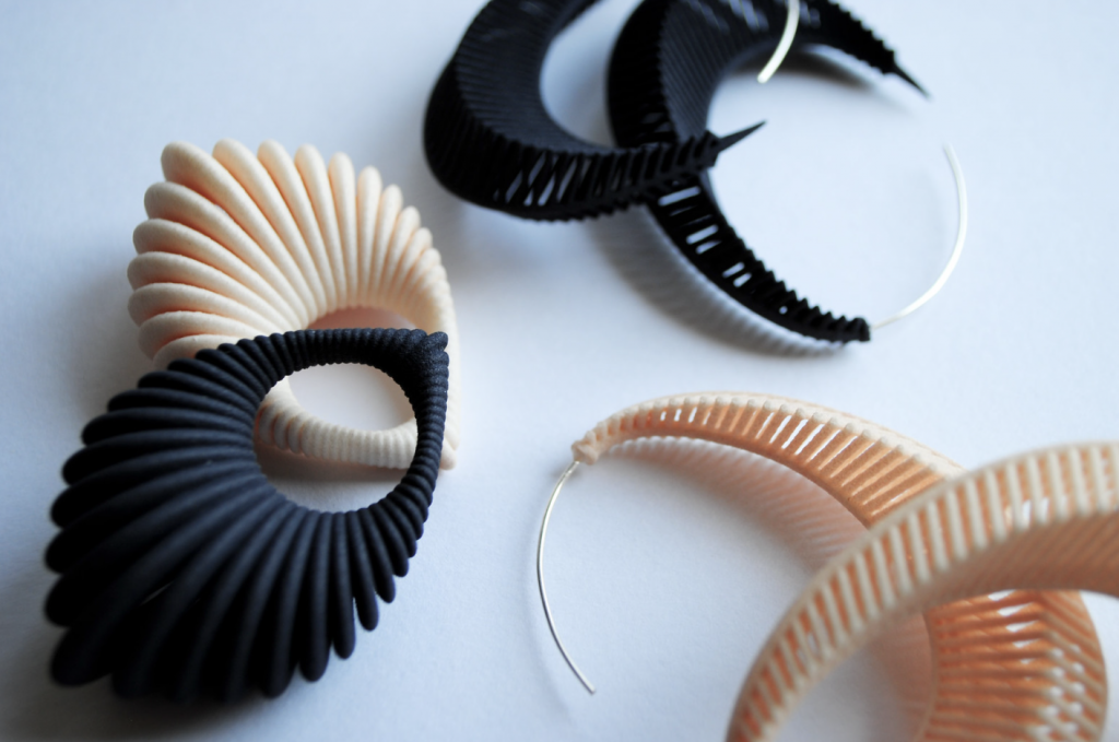
This digital fabrication piece photographed by Theresa Burger not only fascinates me because of its detail and interesting form, but on a broader scale, I really like how the digital fabrication is used as a piece of jewelry and accessory. I think that creating something with the purpose of it being worn and displayed, especially something that is 3D printed, is difficult because the artifact exists for many purposes and is functional, which I admire because of my interests in product design. Like any piece of art, these earrings are stylized and it is clear that the artist has a certain aesthetic. The use of color is very minimal and the form is repetitive in nature which speaks to the artists’ taste for simplicity and minimalism. I think that these earrings follow the rules of a parametric object in that values of a variable are changed and produce a generative design.

Artist: Theresa Burger
Year: 2011
Link: https://www.flickr.com/photos/tweebi/5679733977/in/photostream

Digital Fabrication, Theresa Burger

LO-3: Computational Fabrication

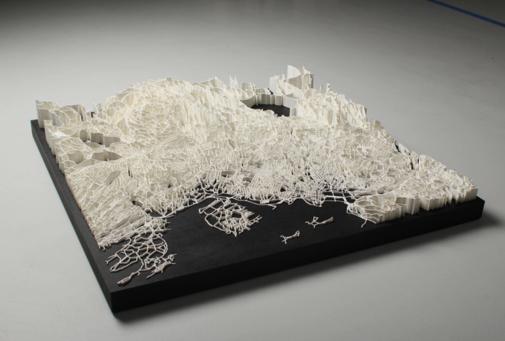
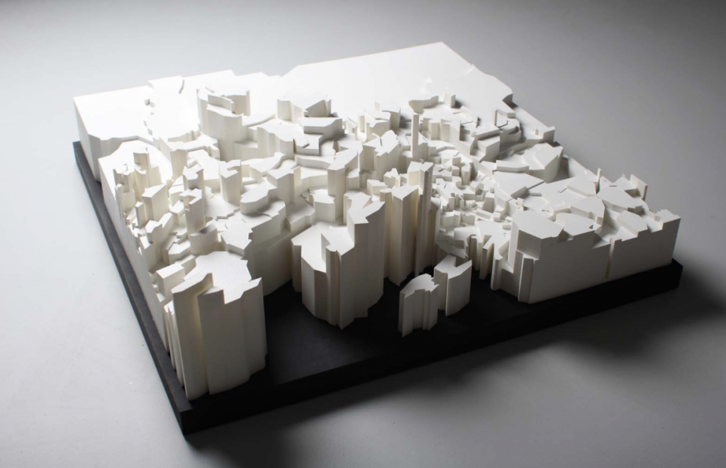
The work “Intersections” by the Bengler team really stuck out to me. The project aimed to create laser sintered sculptures that depicted the map of Oslo, Norway. In one of the maps, they focused on the roads and on the other they took a look at how the map intersected with income statistics. I found it extremely beautiful with the black and white contrast between the map and the ground. It seems so delicate and intricate which just adds to how visually appealing it is. You can tell that the team who worked on this project have artistic tendencies that lean towards simplicity in broad form, but intricacy in details. The website says that they used laser sintered technology to produce this piece. From just googling the process, it seems to be an additive process that binds a material to create a form. I think the algorithm would probably tell the laser at what points to add pieces or bind them together.

Creator: Bengler Team
Title: “Intersections”

http://bengler.no/intersections

Project 3: Dynamic Drawing

sketch

//Jacky Lococo
//jlococo
//Section C
var Rc = 255 // color variables for the moving cirlce, top rectagle, small circles
var Gc = 193
var Bc = 193
var angle = 0
var Rr = 0
var Gr = 60
var Br =  255
var colorChange = 1
var strokeOpacity = 255

function setup() {
    createCanvas(600, 600);
}

function draw() {
    background(255);
    strokeWeight(0);
    fill(Rr, Gr, Br);
    ellipse(160, 160, 200, 200);
    fill(255, 239, 239);
    rect(0, 300, 600, 300); //pink rectangle

    strokeWeight(0);
    fill(Rc, Gc, Bc, 100);
    ellipse(mouseX + 10, mouseY + 10, min (mouseX, 200), min (mouseX,200));
        //shadow of ellipse that follows mouse

    fill(255, 239, 239);
    ellipse(mouseX, mouseY, min (mouseX, 200), min (mouseX,200)); 
        //pale pink circle behind main ellipse

    fill(Rc, Gc, Bc, 200);
    ellipse(mouseX, mouseY, min (mouseX, 200), min (mouseX,200)); 
        //ellipse that follows the mouse and grows smaller at x=200

    fill(Rr, Gr, Br, 200);
    rect(0, 0, 600, 300)
    strokeWeight(0);
    fill(255, 239, 239);
    ellipse(150, 150, 200, 200);
    fill(Rc, Gc, Bc, 200);

    push(); //for top rotating tiny circles
    translate(150, 150)
    rotate(radians(angle));
    ellipse(50, 50, 50, 50);
    angle += 1
    rotate(radians(angle));
    ellipse(50, 50, 50, 50);
    angle += 0.5
    rotate(radians(angle));
    ellipse(50, 50, 50, 50);
    angle +=0 // on circle slower at 0 speed
    if(mouseY > 300){
        angle += 1
    }
    pop();

    push(); // for mouse following rotating cirlces
    translate(mouseX, mouseY);
    rotate(radians(angle));
    ellipse(50, 50, 50, 50);
    angle += 1
    rotate(radians(angle));
    ellipse(50, 50, 50, 50);
    angle += 0.5
    rotate(radians(angle));
    ellipse(50, 50, 50, 50);
    angle += 0
    if(mouseY > 300){
        angle += 1
    }
    pop()

    strokeOpacity = mouseX - 150
    //line that moves - starting from bottom of canvas
    strokeWeight(7)
    stroke(255, 255, 255, strokeOpacity);
    line(100, 0, 100, 600)

    //line that moves - starting from top of canvas
    strokeWeight(7) 
    stroke(255, 255, 255, strokeOpacity);
    line(140, 0, 140, 600)


    //colors alternating with each press if the mouse
    if (colorChange == 1){
        Rc = 255
        Gc = 193
        Bc = 193
        Rr = 0
        Gr = 60
        Br =  255
    }
    if (colorChange == 2){
        Rc = 0
        Gc = 60
        Bc = 193
        Rr = 255
        Gr = 193
        Br = 193
    }
    //text that follows the mouse
    strokeWeight(0);
    fill(255);
    textSize(15)
    text('p r e s s', mouseX, mouseY);
} 

//mouse pressed function that switches the colors
function mousePressed () {
    colorChange = colorChange + 1
    if (colorChange == 3)
        colorChange = 1
    print(colorChange.toString);
}


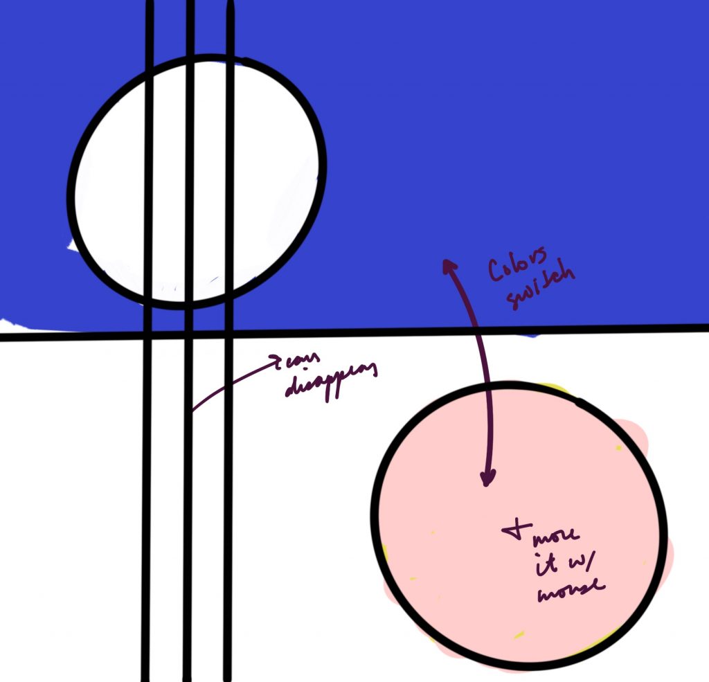
This project was a bit challenging at first, but I think once I had a clear sketch and idea for it, the tasks and process became a lot more manageable.

Sketch:

Project 03: Dynamic Drawing

sketch
// John Henley; 15-104 section D

function setup() {
    createCanvas(500, 500);
}

function draw() {
    background(0);
    strokeWeight(2);
    noFill();
    
    // top-originating lines
    stroke(mouseX/10, 175, mouseY/10);
    curve(width, height, mouseY/10, 0, 500, mouseY, 0, mouseY);
    stroke(mouseX/9, 175, mouseY/9);    
    curve(width, height, mouseY/9, 0, 500, mouseY, 0, mouseY);
    stroke(mouseX/8, 175, mouseY/8);    
    curve(width, height, mouseY/8, 0, 500, mouseY, 0, mouseY);
    stroke(mouseX/7, 175, mouseY/7);    
    curve(width, height, mouseY/7, 0, 500, mouseY, 0, mouseY);
    stroke(mouseX/6, 175, mouseY/6);    
    curve(width, height, mouseY/6, 0, 500, mouseY, 0, mouseY);
    stroke(mouseX/5, 175, mouseY/5);    
    curve(width, height, mouseY/5, 0, 500, mouseY, 0, mouseY);
    stroke(mouseX/4, 175, mouseY/4);    
    curve(width, height, mouseY/4, 0, 500, mouseY, 0, mouseY);
    stroke(mouseX/3, 175, mouseY/3);    
    curve(width, height, mouseY/3, 0, 500, mouseY, 0, mouseY);
    stroke(mouseX/2, 175, mouseY/2);    
    curve(width, height, mouseY/2, 0, 500, mouseY, 0, mouseY);
    stroke(mouseX/1.5, 175, mouseY/1.5);    
    curve(width, height, mouseY/1.5, 0, 500, mouseY, 0, mouseY);
    stroke(mouseX/1.25, 175, mouseY/1.25);    
    curve(width, height, mouseY/1.25, 0, 500, mouseY, 0, mouseY);
    stroke(mouseX, 175, mouseY);    
    curve(width, height, mouseY, 0, 500, mouseY, 0, mouseY);

    // right-originating lines
    stroke(mouseX/10, mouseY/10, 175);
    curve(width, 0, width, height/10, mouseX, 500, 0, mouseY);
    stroke(mouseX/9, mouseY/9, 175);
    curve(width, 0, width, height/9, mouseX, 500, 0, mouseY);
    stroke(mouseX/8, mouseY/8, 175);
    curve(width, 0, width, height/8, mouseX, 500, 0, mouseY);
    stroke(mouseX/7, mouseY/7, 175);
    curve(width, 0, width, height/7, mouseX, 500, 0, mouseY);
    stroke(mouseX/6, mouseY/6, 175);
    curve(width, 0, width, height/6, mouseX, 500, 0, mouseY);
    stroke(mouseX/5, mouseY/5, 175);
    curve(width, 0, width, height/5, mouseX, 500, 0, mouseY);
    stroke(mouseX/4, mouseY/4, 175);
    curve(width, 0, width, height/4, mouseX, 500, 0, mouseY);
    stroke(mouseX/3, mouseY/3, 175);
    curve(width, 0, width, height/3, mouseX, 500, 0, mouseY);
    stroke(mouseX/2, mouseY/2, 175);
    curve(width, 0, width, height/2, mouseX, 500, 0, mouseY);
    stroke(mouseX/1.5, mouseY/1.5, 175);
    curve(width, 0, width, height/1.5, mouseX, 500, 0, mouseY);
    stroke(mouseX/1.25, mouseY/1.25, 175);
    curve(width, 0, width, height/1.25, mouseX, 500, 0, mouseY);

    // left-originating lines
    stroke(175, mouseY/10, mouseX/10);
    curve(0, height, 0, height/10, width, mouseX, mouseY, mouseY);
    stroke(175, mouseY/9, mouseX/9);
    curve(0, height, 0, height/9, width, mouseX, mouseY, mouseY);
    stroke(175, mouseY/8, mouseX/8);
    curve(0, height, 0, height/8, width, mouseX, mouseY, mouseY);
    stroke(175, mouseY/7, mouseX/7);    
    curve(0, height, 0, height/7, width, mouseX, mouseY, mouseY);
    stroke(175, mouseY/6, mouseX/6);    
    curve(0, height, 0, height/6, width, mouseX, mouseY, mouseY);
    stroke(175, mouseY/5, mouseX/5);    
    curve(0, height, 0, height/5, width, mouseX, mouseY, mouseY);
    stroke(175, mouseY/4, mouseX/4);    
    curve(0, height, 0, height/4, width, mouseX, mouseY, mouseY);
    stroke(175, mouseY/3, mouseX/3);    
    curve(0, height, 0, height/3, width, mouseX, mouseY, mouseY);
    stroke(175, mouseY/2, mouseX/2);    
    curve(0, height, 0, height/2, width, mouseX, mouseY, mouseY);
    stroke(175, mouseY/1.5, mouseX/1.5);    
    curve(0, height, 0, height/1.5, width, mouseX, mouseY, mouseY);
    stroke(175, mouseY/1.25, mouseX/1.25);    
    curve(0, height, 0, height/1.25, width, mouseX, mouseY, mouseY);
}

LO3: 3D Generative Designs

John Henley; 15-104 section D.

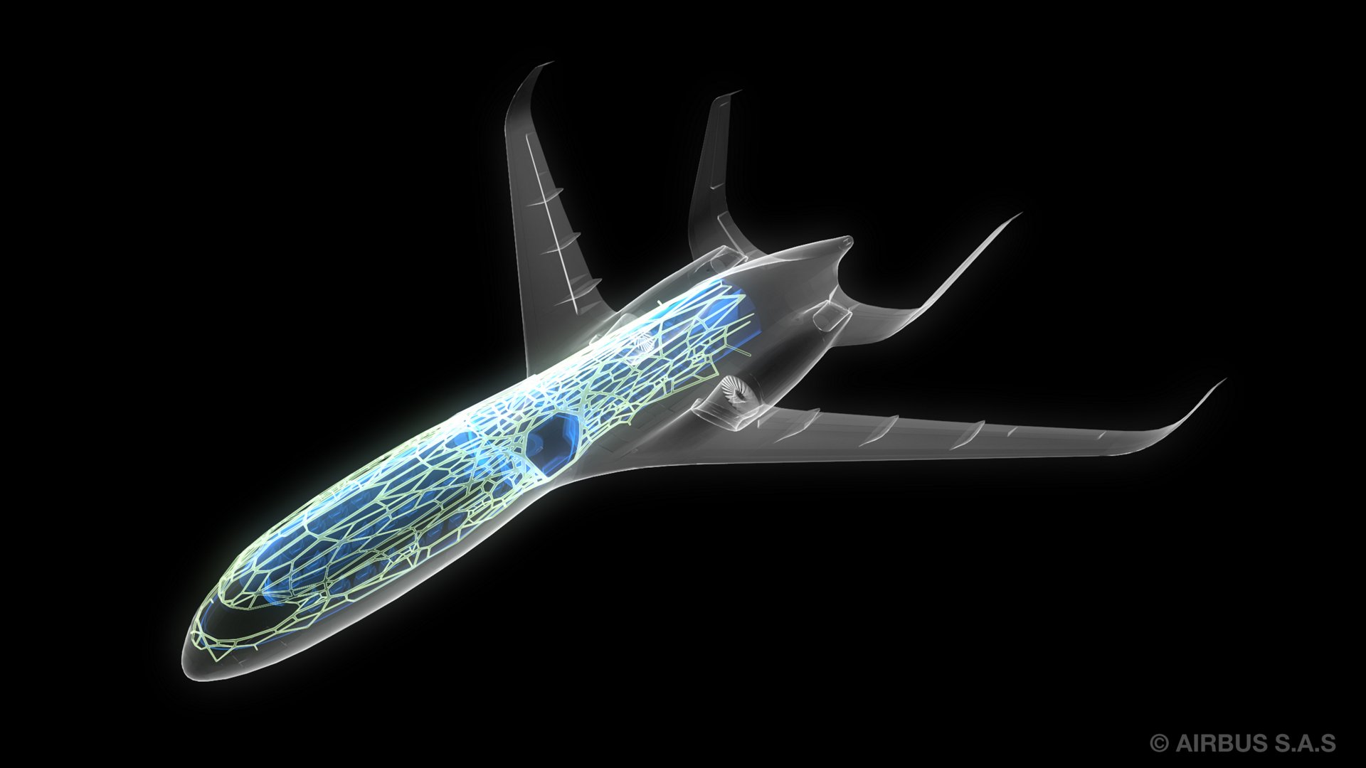
One of my biggest areas of interest in the world industrial design is biophilic design, or designs based off the natural world. A project that combines both generative design and biophilic design that I admire is the Airbus A320 bionic-partition. In 2016, Airbus developed algorithms based on the growth patterns of slime mold to create a new partition dividing the galley from the passenger cabin. The design mimics the single-cell organism’s organic cellular growing structure to create a material that is significantly lighter weight than the previous design. This new design reduces the weight by 55% due to the use of empty spaces evident between cells. In turn, because the aircraft is significantly lighter weight, Airbus claims it can save 465,000 metric tons of CO2 emissions per year. This new design approach is the future–using organic, biophilic-inspired designs in tandem with computer generated production to make the artificial world more efficient and sustainable.

The future by Airbus - The Airbus Concept Cabin Xray: Airbus predicts that the aircraft in 2050 will have a bionic structure that mimics bird bones to allow for lighter weight structure and open panoramic views. (14 June 2011)
Airbus bionic 3D printing, March 2016, Airbus SE.

Link to work: Pioneering bionic 3D printing – Company – Airbus

Project 3 – Dynamic Drawing

gnmarino-03Spacecraft Drawing

var xCord = 300;
var yCord = 225;
var intSize = 1;
//for RBG color values
var intRed = 127;
var intGreen = 0;
var intBlue = 127;

function setup() {
    createCanvas(600, 450);
}

function draw() {
    
    background (200);

    fill(intRed, intGreen, intBlue);

    // Change Red attribute (RGB) color as mouse moves across screen

    intRed = 255 - (mouseX / 2.3529);

    // Change Blue attribute (RGB) color as mouse moves across screen

    intBlue = (mouseX / 2.3529);
    
    //changes size as mouse moves horizontally 
    intSize = xCord * .01


    //if mouse is on left side then spaceship points to the left
    if (width/2 > mouseX) {
        //draws polygon
        beginShape();
            vertex(xCord, yCord);
            vertex(xCord + (5 * intSize) , yCord - (5 * intSize));
            vertex(xCord + (15 * intSize), yCord - (5 * intSize));
            vertex(xCord + (30 * intSize), yCord - (15 * intSize));
            vertex(xCord + (30 * intSize), yCord);
        endShape(CLOSE);

        //if mouse is on right side then spaceship points to the right
    }else {
             beginShape();
                vertex(xCord, yCord);
                vertex(xCord - (5 * intSize) , yCord - (5 * intSize));
                vertex(xCord - (15 * intSize), yCord - (5 * intSize));
                vertex(xCord - (30 * intSize), yCord - (15 * intSize));
                vertex(xCord - (30 * intSize), yCord);
                endShape(CLOSE);
    }


    yCord = mouseY;

   // Don't let object go off canvas if mouseY coordinate goes off canvas
    if (yCord < 0) {
        yCord = 0;
    }

    if (yCord > 450) {
        yCord = 450;
    }

    xCord = mouseX;

   // Don't let object go off canvas if mouseX coordinate goes off canvas
    if (xCord < 0) {
        xCord = 0;
    }

    if (xCord > 600) {
        xCord = 600;
    }


} 


This project was difficult because it was hard to keep track of how the math is working and where your coordinates are, especially while trying to rotate and flip objects.

Also, at first I had a hard time finding an idea that sticks to the parameters and was constricted and always predictable.

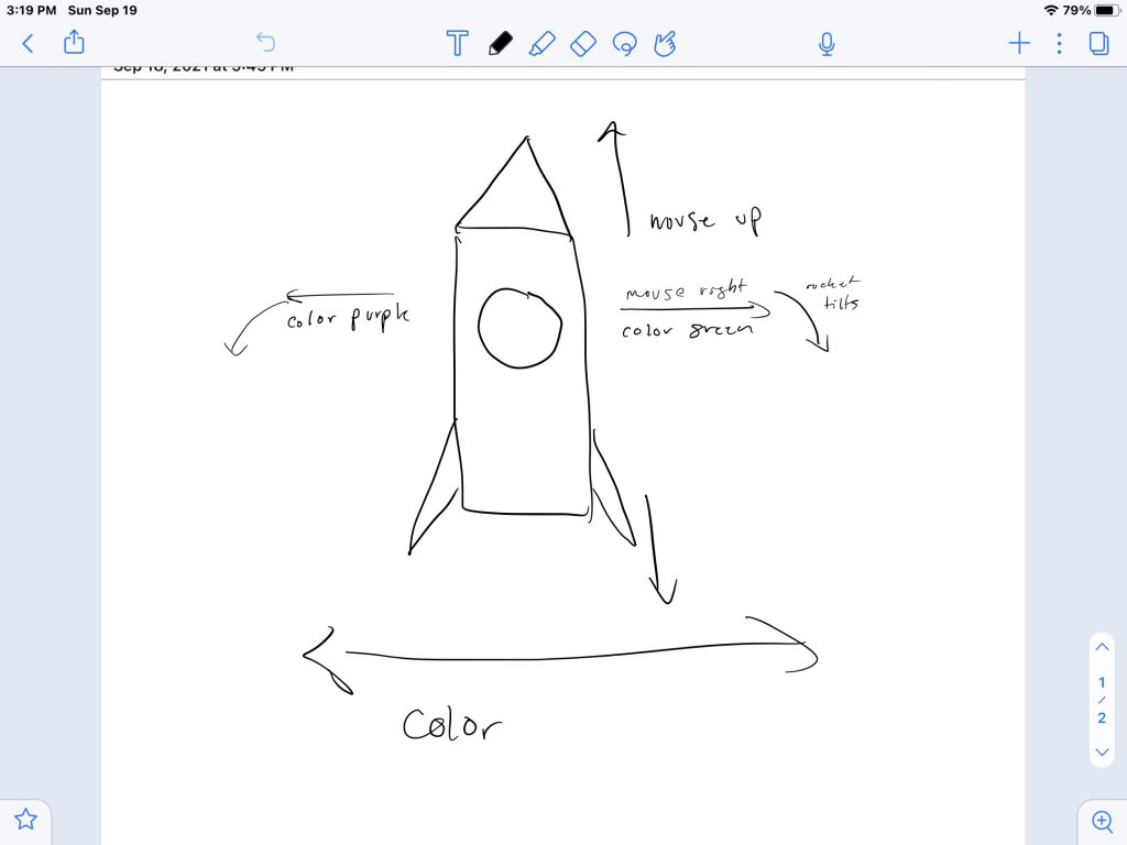
Here is my starting drawing of trying to create my idea.