![[OLD FALL 2017] 15-104 • Introduction to Computing for Creative Practice](../../../../wp-content/uploads/2020/08/stop-banner.png)
// Anna Gusman
// Section A
// Project 03
// This code is a bouncy-bodied, color-changing brush concept.
// Referencing properties of spring and damping forces from p5, I create a brush shape
// that organically changes dimensions as the mouse is dragged.

var centerX = 0.0, centerY = 0.0; // center point of the polygon

var radius = 45, rotAngle = -30;
var accelX = 0.0, accelY = 0.0;
var deltaX = 0.0, deltaY = 0.0;
var springing = 0.0009, damping = 0.98;
//values of the spring and damp forces that make the triangle speed up and slow down when following the mouse.
//
var rr = 10;
var gg= 10;
var bb= 10;
var colorchange = 90;

//dictate the number of nodes
var nodes = 3;

//create zero fill arrays
var nodeStartX = [];
var nodeStartY = [];
var nodeX = [];
var nodeY = [];
var angle = [];
var frequency = [];

// soft-body dynamics
var organicConstant = 1.0;

function setup() {
  createCanvas(600, 400);

  //center shape in window
  centerX = width/2;
  centerY = height/2;

  //initialize arrays to 0
  for (var i=0; i<nodes; i++){
    nodeStartX[i] = 0;
    nodeStartY[i] = 0;
    nodeY[i] = 0;
    nodeY[i] = 0;
    angle[i] = 0;
  }

  // iniitalize frequencies for corner nodes
  for (var i=0; i<nodes; i++){
    frequency[i] = random(5, 12);
  }

  frameRate(60); //increase the drawing speed
}

function draw() {
  //fade the background
  // fill(255, 10);
  // background(200, 3);
  fill(rr, gg, bb); //color of polygon
    rr = 127.5*cos(2*PI*colorchange/360) + 127.5;
    gg = 127.5*sin(2*PI*colorchange/360) + 127.5;
    bb = 127.5*sin(2*PI*(colorchange-20)/360) + 127.5;

colorchange++;
  stroke(0);
  drawShape();
  moveShape();
}

function drawShape() {
  //  calculate the locations of the nodes
  for (var i=0; i<nodes; i++){
    nodeStartX[i] = centerX+cos(radians(rotAngle))*radius;
    nodeStartY[i] = centerY+sin(radians(rotAngle))*radius;
    rotAngle += 360.0/nodes; //drawing 3 points on the circumference of the circle
  }

  // draw polygon
  curveTightness(organicConstant);
  beginShape();
  for (var i=0; i<nodes; i++){
    curveVertex(nodeX[i], nodeY[i]);
  }
  for (var i=0; i<nodes-1; i++){
    curveVertex(nodeX[i], nodeY[i]);
  }
  endShape(CLOSE);
}

function moveShape() {
  //move the center point
  deltaX = mouseX-centerX;
  deltaY = mouseY-centerY;

  // create springing effect
  deltaX *= springing;
  deltaY *= springing;
  accelX += deltaX;
  accelY += deltaY;

  // move the polygon's center
  centerX += accelX;
  centerY += accelY;

  // slow down springing so that the polygon does not continue moving infinitely
  accelX *= damping;
  accelY *= damping;

  // change the tightness of the curves using the organic constant
  organicConstant = 1-((abs(accelX)+abs(accelY))*0.1);

  //move the nodes
  for (var i=0; i<nodes; i++){
    nodeX[i] = nodeStartX[i]+sin(radians(angle[i]))*(accelX*2);
    nodeY[i] = nodeStartY[i]+sin(radians(angle[i]))*(accelY*2);
    angle[i] += frequency[i];
  }
}
For this project, I created an bouncy-bodied, color-changing brush concept. I referenced p5’s softbody dynamics example in order to see how they treated oscillating vector forces. You can find the example here
I was inspired to create a brush concept from the bit of code I wrote in this week’s recitation lab on creating a mouse controlled spiraling ellipse. I first made iterations on this to explore styling options and effects.
Example: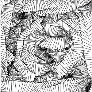
Example:
Still, the brush felt more controlled and predictable than I wanted to to be- I wanted there to be a larger element of surprise. Elements of the soft body dynamics example allowed me to soften the reactions of my shape/brush by giving it springing and damping properties, created by controlling the relationships between the drawn vertexes(nodes) of the shape (curveTightness and curveVertex. This makes the brush wiggle and have a pleasing, natural element to it’s movement. I then control the number of vertexes and sides of the shape and the acceleration and movement of these vertexes. (accel, delta, springing, damping, nodeStart, node).
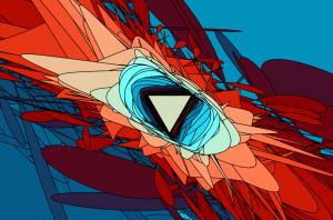
Next I wanted to illustrate change across the movement of the brush path. I did this by creating a color system that undulates across the length of 3 sine waves, one each for red, blue and green.
I also experimented further with eliminating or altering the spring relationship between the mouse and the center of the polygon. Here is one example:
In future iterations of this brush concept, I’d like to embed customization of the brush shape so that when you click, you could alter the number of vertexes that would result in different brush trails. Definitely excited to play around with this more, as it has been a great learning experience.