![[OLD – FALL 2016] 15-104 • COMPUTING for CREATIVE PRACTICE](../../../../wp-content/uploads/2020/08/stop-banner.png)
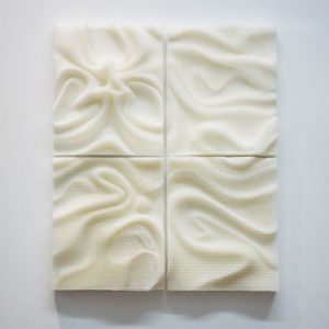
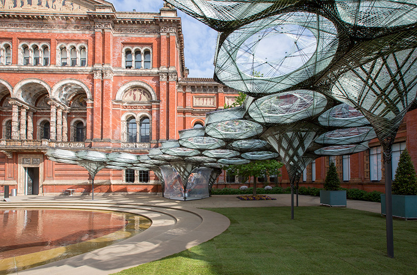
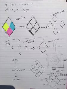
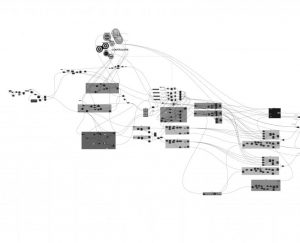
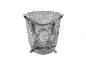
Joris Laarman, a Dutch designer, known for his experimental designs studying variety of shapes, worked on the microstructures series—Soft Gradient Chair, Aluminum Gradient Chair, and Adaptation Chair. The first chair of the project used polyurethane in furniture design by intergrating 3D printing technology in cellular level to specify functions for different needs. Utilizing algorithm based program, Grasshopper in Rhino as shown in the image below, Joris Laarman Lab designed part of the chair to be structurally stable while the rest—more open—acted to give comfort in one print. The second chair is made out of aluminum through Laser Sintering—a generative design tool. Similar to the first chair, the furniture was designed also to specify functions for different needs. Lastly, the third chair known as the Adaptation chair is made out of vertical long module that, like a tree, branch out to form into different geometric shapes to also serve the different needs of the chair. This chair is 3D printed by a SLS machine then coated with metallic material. Through these project, the artist articulate the change of form/shape to adapt to the different needs of a chair allowing comfort as its priority of design.
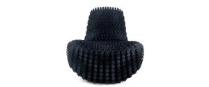
Soft Gradient Chair
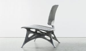
Aluminum Gradient Chair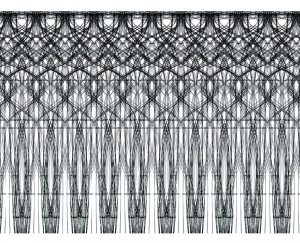
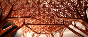
Adaptation Chair