elizabew – looking outwards – 03 – SectionE

Video of the GLASS II Installation Demonstration 

GLASS II from Mediated Matter Group on Vimeo.

GLASS II is a 2017 3D printed glass installation demonstrated in Milan Design week and was made by The Mediated Matter Group. The installation is made out of a series of glass columns made from a computational framework that created each column’s unique form.

What I find incredibly cool about this project is how it pushes the boundaries of glass, a material used in everyday life. While the light aspect isn’t groundbreaking — light and glass has been used as art for a long time — the way they installed a moving light that creates kaleidoscopic images surrounds the columns makes for a further beautiful piece.

The algorithms used to generate these glass columns are, according to the group’s website, “a unique network of radial arrays made of arcs” and the forms are all “directly influenced by the constraints of the manufacturing platform and structural system.” This means that the higher the load on the column, the larger the column gets.

Click here further information on this project

svitoora – 03 Looking Outwards

This chair is designed by a computer. (https://www.wired.com/2016/10/elbo-chair-autodesk-algorithm/)

Computing Optimal Form

If design is truly grounded in the sciences of human factors, then a singular optimal form is identifiable, achievable, and thus computable. The Elbo Chair is an algorithmically generated chair. “Arthur Harsuvanakit and Brittany Presten of Autodesk’s generative design lab created the chair, but they didn’t design it”.

Autodesk Project Dreamcatcher’s parametric algorithmic design. (https://autodeskresearch.com/projects/dreamcatcher)

According to the HFES (Human Factors and Ergonomics Society), many cognitive and physical anthropometric mathematical models already exist, and finding the right design solutions sometimes is a matter of solving an optimization equation. The Elbo chair is an example of an algorithmic optimization design process. By specifying an aesthetic seed “inspirational” from a Dutch chair CAD model, a weight bearing goal for humans, and the ergonomics that the chair must have arm clearances, the chair is thus algorithmically generated. The software keeps on iterating through the algorithm by shaving off dead weight, reducing joinery stress, and material usage. Without a human’s intervention, the design would have gotten bonnier and bonnier. The final result is a combination of algorithmic generation and human intuition. Ocassionally in the process of the software’s countless iteration, a human would pick a design which the software will once against propogate a new lineage of designs based off. “While the look and feel of the final object did not originate in the designer’s mind, it required the designer’s sign-off”. The final form is then CNC and assembled by hand.

The algorithm’s minimized joinery stress for human assembly after CNC fabrication.

https://www.wired.com/2016/10/elbo-chair-autodesk-algorithm/

gyueunp – Looking Outwards 03

Woven Composites was a speculative research that was carried out from 2010 to 2012 by the design director Roland Snooks and the project team of Adrian Cortez, Michael Ferreyra, and Michael Murdock. The research consisted of experiments that provided insight into woven tectonics, which were generated through agentBody algorithms. Woven Composites is an ongoing research that attempts to study “the behavior of components or bodies which have architectural behavior encoded at a sub-agent level.” As the title of the research suggests, the works are composed of what seems to be a complex structure of interwoven elements. The creation of such intricate, plant-like structures that was possible through the process of computational digital fabrication is the most intriguing aspect of this research.

Roland Snooks’ website


egrady-Project03-DynamicDrawing

sketch

//Ean Grady
//section B
//egrady@andrew.cmu.edu
//Project-03

function setup() {
    createCanvas(640, 480);
    background(400-mouseX, 200-mouseY, 300);
}

function mouseMoved(){

    var R = (200-mouseX)/2;
    var G = (600-mouseY)/2;
    var B = 200;
    var Rx = (400+mouseX)/2;
    var Gx = (40+mouseY);
    var Bx = 100
    var Rz = (300+mouseX)/2; 
    var Gz = (80+mouseY);
    var Bz = 50

//the squares on each corner of the canvas
    fill(Rx, Gx, Bx);
    noStroke();
    rect (0, 0, 64, 48)
    rect (576, 432, 64, 48)
    rect (0, 432, 64, 48)
    rect (576, 0, 64, 48)

// the longer rectangles on the side
    fill (Rz, Gz, Bz);
    rect (64, 0, 512, 48)
    rect (64, 432, 512, 48)
    rect (0, 48, 64, 384)
    rect (576, 48, 64, 384)

//code for the ellipse used to draw
    noStroke();
    fill(R, G, B);
    ellipse (mouseX, mouseY, 120, 80);

    sizex=mouseX/2;
    if (sizex>120){
    sizex=mouseX/-4;
};
    sizey=mouseY/2;
    if(sizey>200){
    sizey=mouseY/-4;
};
}


For this project, I wanted to create a canvas for which you could draw something using different shapes. It ended up being a little too ambitious for my programming skills, so I instead created a canvas for which you could use an ellipse to just play around with, where it changes colors as you move it around. I had the most difficult time this week trying to come up with the right code to fit what I wanted, I had to go onto the p5.js reference page a lot, but it definitely helped to familiarize myself with the program.

egrady-LookingOutwards-03

FreeSwim Prosthesis

The “FreeSwim” Prosthesis is a project by Stuart Baynes, an Industrial Design student at Victoria University in New Zealand. The idea behind the project is to utilize computational fabrication and 3-D printing technologies to help alleviate many of the difficulties amputees face in their day-to-day lives, which in this case would be swimming. The FreeSwim Prosthesis is specifically made to aim ‘trans-tibial’ amputees swim, it is a fin-like prosthetic that is attached to the leg, which in turn helps amputees propel themselves in the water and stay afloat, it also similarly helps them get in and out of the pool/water by themselves.

I find this project particularly interesting because it shows the full range of what computational fabrication, specifically 3-D printing, in this case, is capable of. There are so many possibilities out there to explore within the realm of computational fabrication, from architecture and designing furniture all the way to helping the physically disadvantaged.

Laura Rospigliosi (Lrospigl) Project 3

lrospigl_project3

var r;
var t;
var a = 100;
var headx;
var discox;
var p;

function setup() {
  createCanvas(640, 480)

}

function draw() {
  var x = mouseX + (width / 2);
  var y = mouseY;

  background(230, x, y);

  strokeWeight(0);
  fill(a, 200, 200);
  ellipse(r, t, 20, 20);
  ellipse(r * 2, t, 20, 20);
  ellipse(r / 2, -t, 20, 20);
  ellipse(r, t / 2, 20, 20);

  if (mouseIsPressed) {
    ellipse(r, t, 50, 50);
    r = random(20, 500);
    t = random(20, 460);
    a = random(1, 250);
  }

  //disco man
    //shirt
  fill(255);
  rect (headx - 15, 360, 130, 100, 20);
  
  //hair
  fill(40);
  arc(headx + 50, 250, 200, 200, PI-QUARTER_PI, TWO_PI+QUARTER_PI, CHORD);
  //neck
  fill(254, 213, 192);
  rect(headx + 35, 300, 30, 80, 20);
  //face
  fill(254, 213, 192)
  rect(headx, 250, 100, 100, 20);
  //glasses
  fill(0)
  arc(headx + 30, 290, 30, 30, TWO_PI, PI, CHORD);
  arc(headx + 70, 290, 30, 30, TWO_PI, PI, CHORD);
  rect (headx + 30, 290, 40, 5);


  fill(0, 102, 153, 51);
  text("click and drag mouse accross canvas", 5, 480);
  
  if (100 < mouseX & mouseX < (width - 100)) {
    headx = mouseX - 50;
  }
  strokeWeight (0.5)
  fill (255, mouseX)
  ellipse (p, 50, discox, discox)
  
  if (100 < mouseX & mouseX < (width/2)) {
    p = mouseX;
    discox = mouseX/3
  }
    if ((width/2) < mouseX & mouseX < (width - 100)) {
    p = mouseX;
    discox = (width - mouseX)/3
  }
}

elizabew-Project-03-Dynamic-Drawing

Reflection

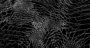
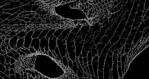
Admittedly, I actually did have a more solid idea before coming up with this program — I was planning on creating a sun going up and down, while make a face squint when the sun was all the way up; however I ended up having too much fun playing around with the patterns and the rotation action that I ended up distancing myself from that initial idea. I found it so exciting to see the patterns that would form depending on how fast it is going and where the mouse was on the image. Overall, the final product reminds me of strobe lights or fireworks — and even though it isn’t as obvious as my initial idea, I still think it looks pretty cool.

sketch

//Elizabeth Wang
//Section E
//elizabew@andrew.cmu.edu
//Project-03: Dynamic Drawing


var angleSecond = 0;
var angleMiddle = 0;
var angleThird = 0;
var angletriangle = 0;
var colorA = 250;
var colorB = 50;

function setup() {
  createCanvas(480, 640);
  rectMode(CENTER);
  angleMode(DEGREES);
}

function draw() {
background(80, 100, 200);

colorA = mouseX;
colorB = mouseY;

noStroke();

//second from middle
fill(200, 100, colorA); // all colors are random, constantly
push();//rotate
translate(mouseX, mouseY); //moves with mouse
rotate(angleSecond);
translate(0, -140); //location
rect(0, 0, 130, 12);
pop();//rotate
angleSecond += max(min(mouseY/10, 1), mouseX/10); //gets faster as you move right

//middle
fill(50, 100, colorB);
push();//rotate
translate(mouseX, mouseY); //moves with mouse
rotate(angleMiddle);
rect(0, 0, 200, 25);
pop();//rotate
angleMiddle += max(min(mouseY/10, 1), mouseX/10); //gets faster as you move down

//third
fill(230, 60, colorA);
push();
translate(width/2, height/2); //doesn't move with the mouse, constant background
rotate(angleThird);
translate(0, 200);
scale (mouseX/100, mouseY/100); // changed size as it moves
rect(0, 0, 220, 35);
pop();
angleThird += max(min(mouseY/10, 1), mouseX/10);

//third but the other direction
fill(200, 200, colorB);
push();
translate(width/2, height/2);
rotate(-angleThird);
translate(0, 200);
scale (mouseX/100, mouseY/100); // changed size as it moves
rect(0, 0, 220, 35);
pop();
angleThird += max(min(mouseY/10, 1), mouseX/10);

//triangle
fill(250, 150, colorA);
push();
translate(mouseX, mouseY);
rotate(-angletriangle);
translate(0, 20);
triangle(-20, 60, 0, 20, 20, 60);
pop();
angletriangle += max(min(mouseY/10, 1), mouseX/10);

//rotating while also going around
fill(150, 200, colorB);
push();
translate(mouseX, mouseY);
rotate(angleSecond);
translate(0, 200);
rect(0, 0, 300, 40);
pop();
angleSecond += max(min(mouseY/10, 1), mouseX/10);


}

Project 03 – Yugyeong Lee

sketch

//Yugyeong Lee
//Section B
//yugyeonl@andrew.cmu.edu
//Project-03

var y = 0;
var spacing = 15;
var r = 7.5;

function setup() {
    createCanvas(640, 480);
}

function draw() {
	noCursor();

	//background color change based on position of mouseX and mouseY
	colorR = map(mouseY, 0, height, 180, 255);
	colorB = map(mouseX, 0, width, 180, 255);
	colorG = map(mouseX, 0, width, 160, 235);
	background(colorR, colorG, colorB);

	//strokewegith depends on the position of mouseY
	m = map(mouseY, 0, height, 1, 5)
	strokeWeight(m);
	stroke(255);

	//array curves with mid points that react to position of mouseX and mouseY
	if (mouseX >= width/2) {
		for (var i = 0; i < 640; i+= spacing) {
			positionX = map(mouseX, 0, width/2, 0, 1);
			positionY = map(mouseY, 0, height, 0, 1);
			noFill();
			beginShape();
			curveVertex(i,  0);
			curveVertex(i,  0);
			curveVertex(positionX*i, height*positionY);
			curveVertex(i, height);
			curveVertex(i, height);
			endShape();
		}
	}

	//array of curves stay straight when mouseX is on left half of canvas
	if (mouseX < width/2) {
		for (var i = 0; i < 640; i+= spacing) {
			line(i, 0, i, height);
		}
	}

	//array of circles
	for (var x = 0; x < width + r; x+= spacing) {
		for (var y = 0; y < height + r; y+= spacing) {
			noStroke();
			//the amount of circles which changes size depends on mouseX
			var n = map(mouseX, 0, width, 1, 8);
			//aray of circles which changes color based on its distance from the Cursor
			if (dist(mouseX, mouseY, x, y) < n*r) {
				fill(random(0, 255), random(0, 255), 200);
				r = 12
			}
			else {
				fill(150);
				r = 7.5
			}
			ellipse(x, y, r, r);
		}
	}
}


I wanted to create a grid base, interactive graphic that depends heavily on the position of mouseX and mouseY. The array of circles’s sizes and color depend on the distance between position of the cursor and the center point of each circle. The background color also changes based on mouseX and mouseY as well as the array of lines in the background in which the mid point changes value based on location of the cursor as well.

keuchuka-lookingoutwards-03


Underwood Pavilion / Muncie, Indiana / 2014

Construction Sequence

Pavilion and Human Scale

Underwood Pavilion

This project, created in 2014, located in Muncie, Indiana, is by professors Gernot Riether and Andrew Wit, working in a digital design build studio in Ball State State University in Indiana. The structure is composed of fifty-six three-strut tensegrity modules. By parametrically adjusting their dimensions, the designers were able to control both the curvature of the pavilion and the size and shape of several openings that frame views of the site. The structure is made of fifty-six three-strut tensegrity modules. The designers were able to control both the curvature of the pavilion and the size and shape of openings that frame views of the site by parametrically adjusting their dimensions (i think this is done through a 3d modelling program like Rhino and a parametric controller like Grasshopper). The tensile material wrapped over the rigid parametric structure, which makes it look more delicate and balanced as a space that considers the climate and users. It’s interesting to see how flexible this structure is, as it is made of modules, therefore it is easy to transport and change according to different sites or purposes; it is also capable of being moved and set up in other sites quickly, therefore creating destinations promptly.

ashleyc1-Section C-Project-03-Dynamic-Drawing

sketch

//Ashley Chan
//Section C
//ashleyc1@andrew.cmu.edu
//Project-03-Dynamic-Drawing.


//PARAMETERS THAT I AM CHANGING
//Color
//Ball Size
//Ball angle: rotation of the spiral
//Spacing between balls
//Size of spiral

    var angle;
    var positionX;
    var positionY;
    var ballWidth;
    var ballHeight;
    var isDrawing;
    var r;
    var g;
    var b;

//setup with default values for rgb color values
function setup(/*red = 213, green = 23, blue = 23*/) {
    createCanvas(640, 480);
    background(0);

    //rotate circles based on mouse position
    //#gotta love trig 
    angle = (atan((mouseY - 240) / (mouseX - 320)) / 500);
    
    positionX = 0;
    positionY = 0;
    ballWidth = 5;
    ballHeight = 5;

   //as you increment i, draw a circle
    for (var i = 0; i < 600; i++) {

        fill(r, g, b); 
        stroke(255);

        //As i increases, we draw a ball with increasing width
        //untill we reach maximum growth
        ballWidth += (30/600) * ((480 - mouseY) / 480);
        ballHeight += (30/600) * ((480 - mouseY) / 480);

        //start point
        push();
        translate(width/2, height/2); 
        rotate(degrees(angle));
        ellipse(positionX, positionY, ballWidth, ballHeight);
        pop();
    
    
        drawOut();

    }
    

}

function draw() {

    changeColor();

}


function changeColor() {

    //if mouse is on right side of canvas, red
    if (mouseX > width/2) {

         r = map(mouseX, 0, width/2, 500, 213);
         g = map(mouseX, 0, width, 100, 32);
         b = map(mouseX, 0, width, 135, 255);

}
    //if mouse is on left side of canvas, blue                              
    if (mouseX < width/2) {
        
         r = map(mouseX, 0, width/2, 200, 100);
         g = map(mouseX, 0, width, 0, 32);
         b = map(mouseX, 0, width, 0, 255);

    }

    //have to call setup again if you want movement
    setup(r, g, b);

}


function drawOut() {
   //circles drawn outward

    positionX = positionX  + .5;
    positionY = positionY + .5;

    //controls the spacing between the balls 
    angle = angle + (mouseX/ 100000);


}

For this project, I wanted to expand on the spiral drawing exercise we did in lab because I found it a fun shape to play with and thought it would create a cool optical illusion. Although subtle, I am changing several parameters such as color, ball size, ball position and angle as well as the space in between the balls. One surprising result is how much had to tap into old trig knowledge in order to calculate how to rotate the spiral just right.