![[OLD FALL 2017] 15-104 • Introduction to Computing for Creative Practice](https://courses.ideate.cmu.edu/15-104/f2017/wp-content/uploads/2020/08/stop-banner.png)
var angle = 0;
var m = 0;
var n = 0;
var size = 0;
var sizen = 0;
var x = 0;
var z = 0;

function setup() {
	createCanvas(640, 480);
}

function draw() {
	x = max(min(mouseX, 255), 0);
	z =max(min(mouseX, 255), 0);
	background(0);
	fill(x, 255, z);
	ellipseMode(CENTER);

//create ellipse with color dependent on where the mouse is

	m = max(min(mouseX, 640), 0);
	n = max(min(mouseY, 480), 0);
// //setting the x and y coordinates to be the max value between the mouse coordinates and the canvas size

	size = m * 350 / 400;
	sizen = n * 350 / 400;
	//settin the size of the ellipse to be a function of the position of the coordinates


	push();
	ellipse(mouseX, mouseY, size, sizen);
	//using the variables to create an ellipse
	fill(x, 255, z);
	//filling the color for the ellipse based on where the mouse is on the canvas
	translate(mouseX,mouseY);
	//moving the ellipse based on where the ellipse is in the canvas
	rotate(radians(angle));
	//rotating the ellips
	pop();
	angle = angle +5;
} Month: September 2017
ghou-project-03-DynamicDrawing
//Grace Wanying Hou
//15-104 Section D
//ghou@andrew.cmu.edu
//Assignment 03
var br;
var bb;
var bg;
var ss;

function setup(){
    createCanvas(640,480);
    rectMode(CENTER);
    background(255);
    //base text
    br = width/6 + 30;
    bb = height/4 + 100;
    bg = 200;
    //setting colour of the text so it blends in with that region of colour
    textSize(30);
    fill(br,bb,bg);
    text("drag mouse to draw",200,400);
}
ss = 0;
//creating the heart
function draw(){
    fill(255);
    noStroke();


    // heart changes size when drawing (mouse is pressed)
    // heart creates gradient colour the bigger it is
    if (mouseIsPressed){
        if (ss < 1.5){
            ss = ss +0.005;
            fill(255,255-ss*170,255-ss*170)
        }
    }
    //creates gradient when heart shrinks
    else if (ss >0){
        ss = ss - 0.02;
        fill(255,255-ss*200,255-ss*200)
    }
    // heart is red when at largest and text appears to tell audience to let go of the mouse
    if (ss >= 1.5){
        push();
        fill(255);
        text("let go!!",280,70);
        pop();
        fill(255,0,0);

    }

    push();
    translate(width/2,height/2);//so the posotion doesnt get messed up as it scales
    scale(ss);
    ellipse(-55,-30,130,150);
    ellipse(55,-30,130,150);
    triangle(-105,19,0,130,0,0);
    triangle(105,19,0,130,0,0);
    pop();
}

//drawing with the mouse (in gradient colour)
function mouseDragged(){
    br = mouseX/6 + 30;
    bb = mouseY/4 + 100;
    bg = 200;
    noStroke();
    fill(br,bb,bg);
    ellipse(mouseX,mouseY,80,80);
}
in my sketchbook I included some sketches on how to do the layering so that the text hides behind the “drawing”.
This dynamic drawing is inspired with social media “Likes”, I had originally wanted my audience to double-click for the heart to appear, as it represents a double tap on social platforms. However, I could not get the doubleClicked() function to work and it could be something in the DOM file that I’m not knowledgable enough to get into. I figured the gradient is a pretty way to impress the audience.
dnam-Looking Outwards-03
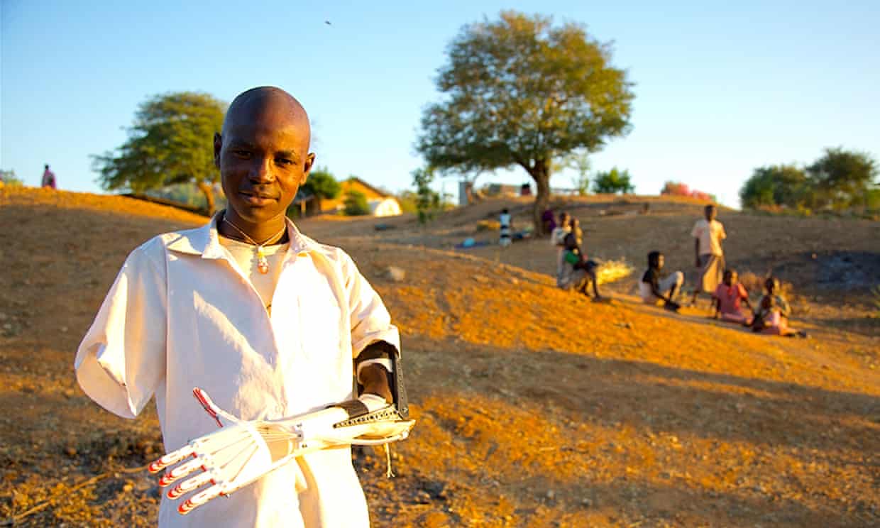
Technology has developed greatly in the medical field. Computation fabrication has allowed a new door for prosthetic limbs. Ian Birrell, in the Guardian Article written in February 2017, discusses the story of Ivan Owen, an artist who helped others by creating 3D models of prosthetics. One of the story shared was about Liam, a five-year old with missing fingers. While Owen knew he could make the prosthetics fairly easily, the concern of Liam’s rapid growth bothered him. Therefore, Owen made a 3D prosthetics model that could be resized and reprinted whenever needed. This allows Owen to always change the fit of the prosthetics as needed, as well as be able to produce it in a cheaper method than hand creating the object himself. Computational fabrication has allowed for more people to have access to prosthetics, helping those in need.
juyeonk – Looking Outwards – 03
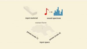
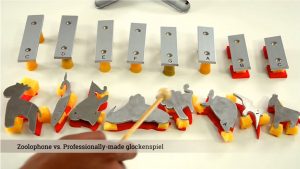
Title: Computational Design Of Metallophone Contact Sounds
Creator: Gaurav Bharaj, David I.W. Levin, James Tompkin, Yun Fei, Hanspeter Pfister, Wojciech Matusik, Changxi Zheng
Year of Creation: 2015
Link to the project: http://cfg.mit.edu/content/computational-design-metallophone-contact-sounds
This project is intended to explore the manufacturing process of metallophones of various shapes and sizes. Previously, professionally designed metallophones came only in the shapes of bars, and the collaborative team from Harvard, MIT and Columbia tried to come up with a way to produce metallophones of not only unique appearances but sounds as well. They invented an algorithm to deform and perforate metals of random shapes to optimize the sounds that they produced when struck. They believed the new method would enable non-professionals to make their own, unique metallophones as well.
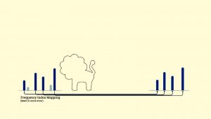
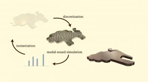
Doing so requires an extensive exploration of the energy landscape. They first mapped the sound spectrum that the metal piece produced and compared it to the desired sound spectrum that they wanted the metal piece to produce. Then using the algorithm that allows the isotropic scaling of the metal piece in relation to the desired change in the sound spectrum and through the repeated process of discretization and instantiation, the team could produce a new piece of metal with an ideal sound spectrum. Using the same method, they could also have multiple tones and chords produced from a single metal piece.
sntong-Looking Outwards-03-Computational Fabrication
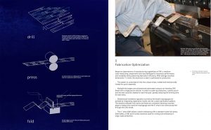
Evaporative Folding by Jeana Ripple (project architect), Ryan Lewandowski and Hossein Haj-Harriri + Mehdi Sadaat (consultant) uses computational techniques to customize the production of aluminum modules that creates an effective facade for evaporative cooling for houses in hot and dry climates. By optimizing material properties and manufacturing processes for aluminum, the team was able to generate an effective “cooling” facade that is durable, mold-resistant and can also act as an passive solar heat gain element during the night. The computational processes in the project is used to determine location, size of holes that are then CNC into the aluminium panels to create the perforation pattern suited for the house in the specific location.
It is inspiring to see the possible elegant solutions that computational processes are allowing architects and engineers to address environmental issues. Not only the project is successful in demonstrating what computational fabrication can do for the construction industry, it also shows that architects can design smarter buildings that are more energy efficient.
(image source: http://ripplearchitecture.com/Evaporative-Skin)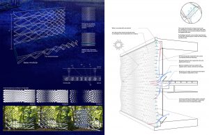
Looking Outward 3
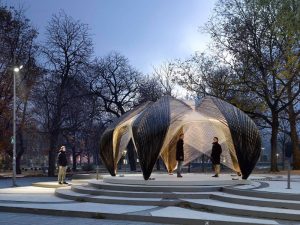
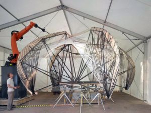
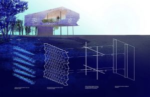
The Institute for Computational Design (ICD) and the Institute of Building Structures and Structural Design (ITKE) at the University of Stuttgart construct a research pavilion every year since 2010. The one that I admire the most, however, is not the latest and most complicated one, but the 2012 one. In November 2012 ICD and ITKE have completed a research pavilion that is entirely robotically fabricated from carbon and glass fibre composites. What I admire is that “the research focused on the material and morphological principles of arthropods’ exoskeletons as a source of exploration for a new composite construction paradigm in architecture”. When I was watching the Vimeo video that records the procedure of the model making. I feel that robots and computing really take a big part in the future architecture. I am an architecture major student, so I am really curious about the future trend of buildings. This pavilion makes me feel very excited because using robots are actually helping architects to build a bigger dream. When using robots, your models can be in a much larger scale in a higher level of precision and elaboration. It can reduce the amount of labor and improve the efficiency. Also, it can human’s thoughts into In the video, they also show that they are using Grasshopper, a plug-in, in Rhino to control the robots. I am now taking the Grasshopper course which makes me more excited about this. We also need to learn about coding, python, in grasshopper to write programs to make a model. I think this project really gives me the direction, inspiring me what grasshopper and robots can do to achieve your dream, and guides me to go further and further with technology. .
ENwandu-Looking Outwards-03-Silk Pavilion
Silk Pavilion – MIT Media Lab
Director of Project – Neri Oxman
Team Members: Markus Kayser, Jorge Duro-Royo, Jared Lauks
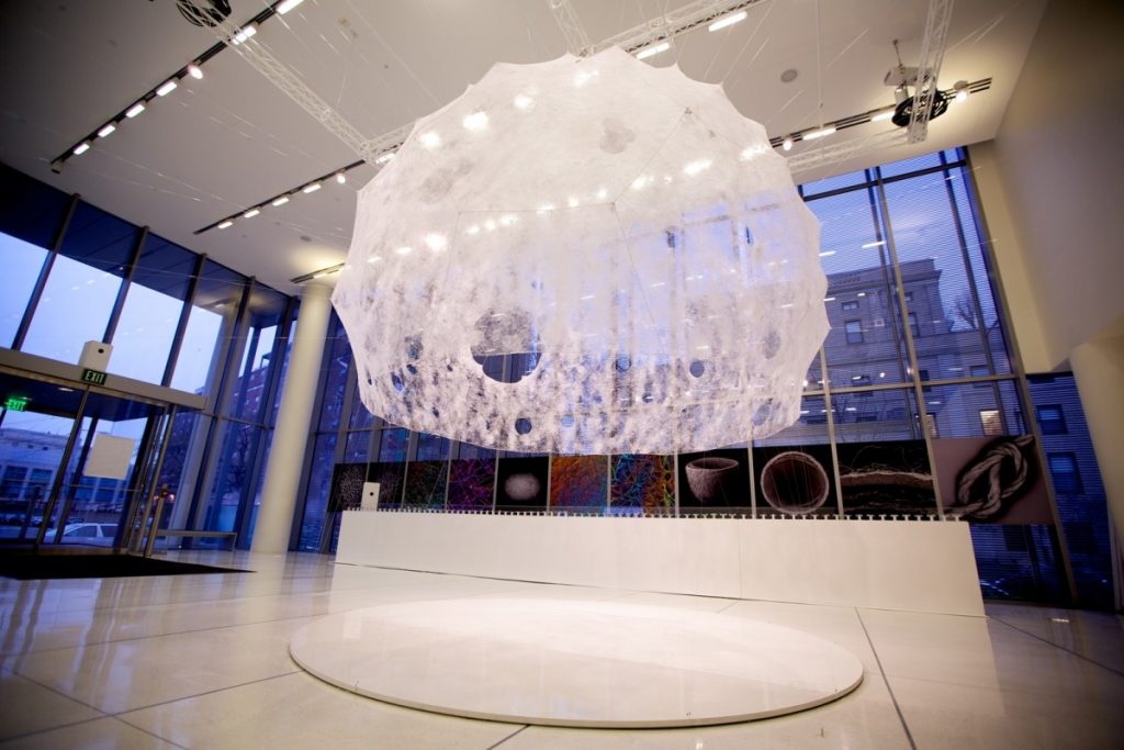

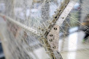
The silk pavilion is a very intriguing (slightly disgusting) project, not simply because of its computational fabrication, but its connection to biology. The research carried out by the group focused on the integration of computational form finding techniques with biologically inspired formations. Inspired by the way silk worms weave delicate cocoons, the pavilion was created using a base of robot-woven threads wrapping a steel frame. Ultimately, the structure was completed by unleashing 6500 live silkworms onto the primary structure. Before the primary structure was built, the team involved with the project delved into some painstaking research, into the silkworm’s interaction with their environment, and methods of weaving their cocoons. This involved observing them in a variety of 3D spaces under different ambient conditions to utilizing motion tracking equipment to examine the construction process. The patterns computed by tracking the silk worms directly influenced the path the CNC mill would take when fabricated the primary structure. The pavilion’s overall geometry was created using an algorithm that assigns a single continuous thread across patches, providing various degrees of density
I really admire this project, because of the bio-mimicry involved. The project is one that truly encompasses the ideas of information technology and biology. We see the geometric frames used, alongside a technologically interpreted natural process. Both species involved with the project have a voice, but its intriguing how seamless they are. The researchers’ eve observed that the “blind instinct of the silk worm is sometimes almost machine-like”. I see projects like this becoming influential in a conversation about what art, architecture, and design can become in the future, by considering how natural order, and processes can inform our design decisions.
rkondrup-Looking-Outwards-03
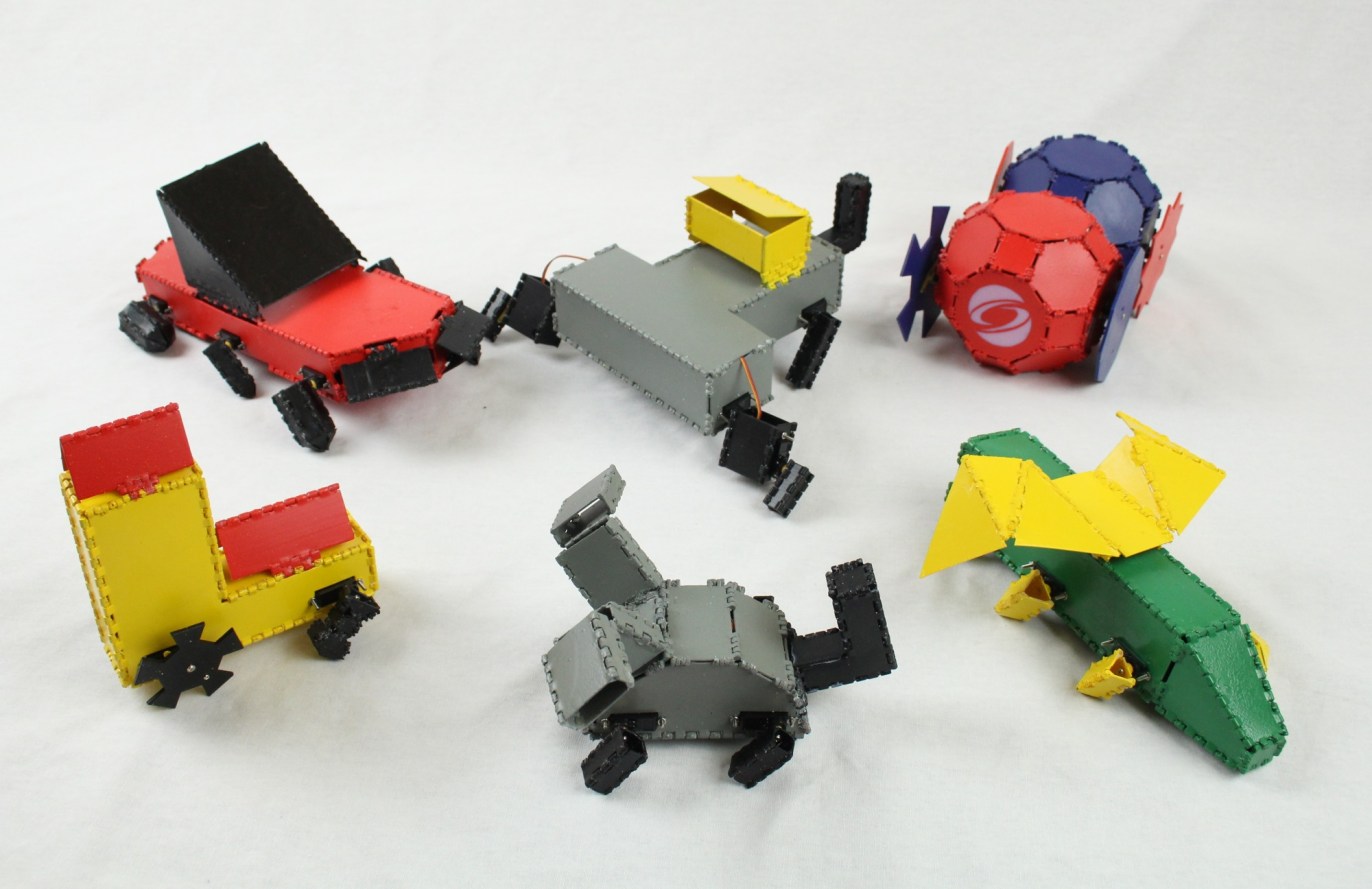
Students at MIT have developed what they call “Interactive Robogami,” a project which allows users to 3D print motorized origami creations which can move, walk, or roll. The design consists of an easy-to-use user interface which allows participants to design a structure with features like legs and wheels, while the program calculates speed, direction, and timing of moving parts internally. Completed designs were then sent to the 3D printer for fabrication. Designs were printed as a flat bunch of pieces which are then assembled or “folded” into the desired shape to produce a functional object.
This project is very interesting to me because it combines many different technologies into a single experience. The Robogami consists of complex software, friendly user interface, digital fabrication, origami, and moving parts; this requires a large amount of thinking and collaboration. In addition, I am very interested in how this technology could be scaled up over time, possibly to the transportation or housing level in the far future. This project gives amazing design power to consumers which has never been available before – perhaps in the future users will be able to custom-design their own headphones, cars, or even homes, and have built-in interactive features automatically integrated into the design.
cespinoz-Looking Outwards 02
For this assignment I chose Memo Akten’s Fight (2017). Fight uses Virtual Reality and Binocular Reality and transforms it into interpret art right in front of the eye. I chose this piece because virtual reality, to me, is one of the most fascinating advances in technology. I vividly remember my first experience with virtual reality, and always yearn to experience it again when possible. What I particularly like about this piece though, is its variability aspect in which each viewer has a different visual experience despite the images displayed being the same every time.
Though I’m not quite sure on how Atken made the images, I know that at a basic level, virtual reality works by using a stereoscopic display that allows eyes to see depth into the images projected. The images that Atken chooses for this piece are ones that do not directly match our expectations of the outside world.
Attached is a video of one of infinite visual experiences from Fight
In his interviews, Atken draws his main purpose of this piece is to think about perception. He writes, “perception, including vision, is an active process, it requires action and integration”. More information about Memo Atken’s Fight can be found here: http://www.memo.tv/fight/
cespinoz-project-02
var cheekWidth = 125
var cheekHeight = 125
var leftEyeX = 285
var rightEyeX = 365
var leftEyeY = 170
var rightEyeY = 170
var toothHeight = 40

function setup() {
    createCanvas(640,480);
}
function draw() {
    background(255,217,223);
    noStroke();
    fill(139,69,19) //squirrel tail
    rect(345,150,200,325,90,10,95,0)
    fill(153,102,51); //face and body color
    ellipse(320,200,200,200) //top head
    ellipse(320,280,160,190) //CHIN
    ellipse(260,275,cheekWidth,cheekHeight) //left cheek
    ellipse(380,275,cheekWidth,cheekHeight) //right cheek
    triangle(240,80,240,140,280,120) // left ear
    triangle(400,80,400,140,360,120) // right ear
    rect(250,335,140,225,10,10) //body
    fill(145,95,50) //color for feet
    ellipse(250,475,100,75) //left foot
    ellipse(385,475,100,75) //right foot
    ellipse(250,375,60,60) //left hand
    ellipse(385,375,60,60) //right hand

    fill(97,65,38) //acorn
    triangle(260,375,375,375,320,420)
    rect(310,355,20,20,5,5)
    fill(112,84,59)
    rect(260,365,115,15,10,10)

    //squirrel face
    fill(256);
    ellipse(280,180,65,65)
    ellipse(360,180,65,65) //white eyes
    fill(0);
    ellipse(285,180,55,60) //left color eye
    ellipse(365,180,55,60) //right color eye
    fill(256);
    ellipse(leftEyeX,leftEyeY,30,30) //left pupil
    ellipse(rightEyeX,rightEyeY,30,30) //right pupil
    fill(0) //nose
    ellipse(320,250,75,25) //round nose
    rect(315,250,10,40,5,5) //nose vertical line
    ellipse(320,290,125,5) //mouth
    fill(256) //teeth
    rect(290,292,29,toothHeight,5,5) //left tooth
    rect(320,292,29,toothHeight,5,5) //right tooth

}

function mousePressed() {

    cheekHeight = random(100,150);
    cheekWidth = random(100,150); //cheeks change
    leftEyeX = random(275,295) //now eyes change
    rightEyeX = random (355,375)
    leftEyeY = random(170,190)
    rightEyeY = random(165,190)
    toothHeight =random(30,50)


}
I decided to use a squirrel for my variable-changing face project. To begin, I sketched out an idea of the main head and face onto notebook paper as shown here: 
As I started coding, I got more confident with the axes and began to do a fast guess and check as my program got more detailed. I then chose to have the variables of the teeth, pupils, and cheeks change.